56-101-01175 Revision H Page | 25
2. POSITIONING
It is important whether testing on the aircraft or on the bench that the Test Set be positioned
so as to not impede the ability to quickly power down and or disconnect electrical power
should the need arise.
3. ACCESSORIES
A. Items included
1. Instruction Manual P/N 56-101-01175, see Figure 12.
2. Electrical Cable P/N AE9887-ND, see Figure 13.
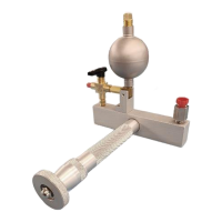
3. Hose Kit P/N 115-00632, see Figure 14.
4. Wi-Fi Antenna P/N 126-00001, see Figure 15.
5. Carrying Bag P/N 195-00020, see Figure 16.
6. AN4 Caps with Lanyard, P/N 176-00001 (OPT-A), see Figure 17.
Used for Wi-Fi communication. This feature can be
used to communicate with either an android or iOS
tablet.
Used to ensure Test Set chassis is at same ground
potential as the Aircraft or Instrument being tested.
Connects external power to the tester. Unit uses either a
cable with a standard 115 VAC plug or the optional
cable for operator installation of 230 VAC plug.
Power entry module fuses.
For 120 VAC operation use 1(ea) fuse: 4A
For 220 VAC operation use 1(ea) fuse: 2A
Used to power On/Off Test Set operation
Standard USB port used for multiple purposes
To Upgrade Test Set HUIM or PCM Firmware
from flash drive. Please refer to Appendix F for
the Field Firmware Update Procedure
To download Test Set history log contents onto
USB flash drive.