56-101-01175 Revision H Page | 33
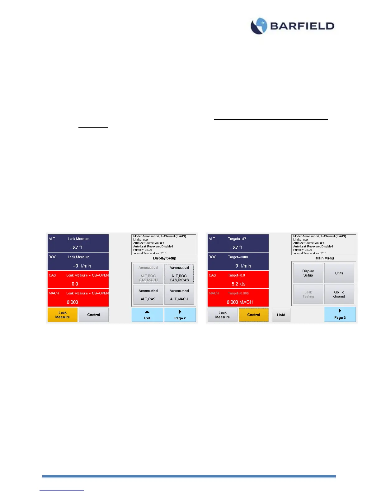
1. The left-half of the screen is dedicated to providing all the measurement and control
display screens.
2. The right-half of the screen is dedicated to providing all the menu displays and
selections
3. The top right-quadrant is used to display Test Set operational status (Mode, Limits,
Altitude Correction, Auto Leak Recovery) information.
4. The Leak Measure and Control mode soft-key will have an amber background
indicating which mode the Test Set is presently operating in (see Figure 23).
5. While in Leak Measure mode, “Target =” is not displayed for any of the 4-parameters
or 2-parameters displayed and therefore the touch zones for those parameters are
not active.
6. While in Control mode, the 4-parameters or 2-parameters displayed will have a
“Target =” value displayed, when the Test Set transitions from Leak Measure to
Control mode the Target value(s) are automatically set to the present value
measured on the Ps & Pt ports. During the transition to Control mode, “Wait
Resuming Control” is displayed and ALL touch screen zones are disabled except for
the “Cancel” soft-key. When the message “Wait Resuming Control” disappears the
pneumatic controller has achieved pressure equalization with the current pressure on
the Ps & Pt ports. At this time the 4-parameter or 2-paramter touch zones are active
and the user can enter Target values for each of the displayed parameters.
7. While in Control mode, the Leak Testing soft-key is ghosted. Leak testing can only
be accomplished while in Leak Measure mode.
Figure 22 Display Setup Aeronautical Menu
Note: Regarding the UI Menu structure, the menu screen above is considered the
top level “Root Menu”.
Note: Throughout this section while explaining all the UI related functions the soft-
key (touch screen) sequence will be listed based on starting at the top level
“Main Menu” position.
8. While in Control mode, the user can specify the Target value(s) by simply touching
the pane touch zone area for the Target parameter of interest. For example, see
below for ALT, ROC, CAS, MACH display setup. The user can enter the Target
value for any of the 4-parameters by initially touching the parameter touch zone area,
which will cause the Target keypad to be displayed for user entry. For this example
the ALT touch zone was selected.
9. While in Leak Measure mode, the touch screen is not active for any of the 4-
parameters. Only the right half side of the screen, the Leak Measure mode and the
Control mode soft-keys are active.