56-101-01175 Revision H Page | 92
Appendix F: IBF System Mode
The following appendix details the configuration and usage of the unit when setup to perform in
IBF (Inlet Barrier Filter) Mode.
The purpose of the IBF is to protect the turbine engine from foreign damage and micro erosion
when operating in normal and severe environmental conditions.
To access IBF system mode:
1. Power unit “On”. Allow the unit to go through the initialization process.
2. Connect the standard Static (Ps) channel hose to the Test Set.
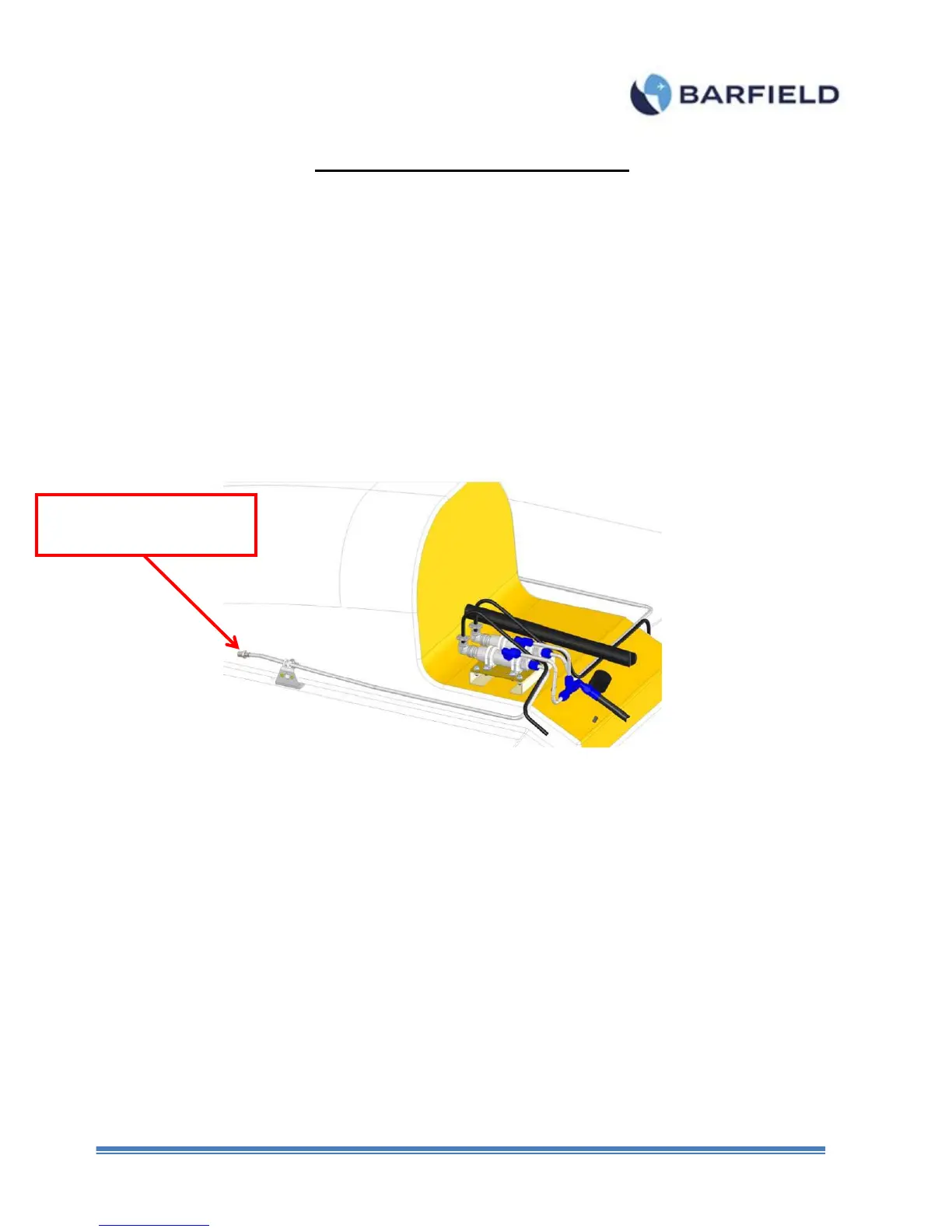
3. Connect the IBF accessory hose (P/N: 115-00644) to the end of the Static (Ps)
hose (Figure F.1).
Figure F 1 Low Pressure Hose
4. Connect the open end of the IBF accessory hose to the Low Pressure Port
5. From the “Main Menu”, touch “Page 2”. A screen is displayed with 4 options (Figure
F. 2).