56-101-01175 Revision H Page | 50
proportional control valves and the transducers. During this test, the unit’s internal
manifold mounted output valves SvPs_Out and SvPt_Out are closed (refer to
DPS1000 Internal Pneumatic diagram, Appendix C), and therefore the Ps and Pt
Output reservoirs are not included in this test.
6. The Vacuum and pressure pumps are tested to verify they are able to achieve the
performance expected.
7. The initialization display window and log file includes the Test Set’s power on cycle
count: # of hours the Test Set has been powered ON, # of hours on the pressure
pump, # of hours on the vacuum pump.
8. At the end of the initialization cycle the Test Set performs a Go to Ground to ensure
both the STATIC (Ps) and PITOT (Pt) ports are at ambient pressure.
Note: During this power ON initialization Go To Ground phase the Target ROC will
default to a very low rate (2,000 ft/min), the user can change the ROC for that
occurrence by pressing the ROC touch zone and changing the Target value.
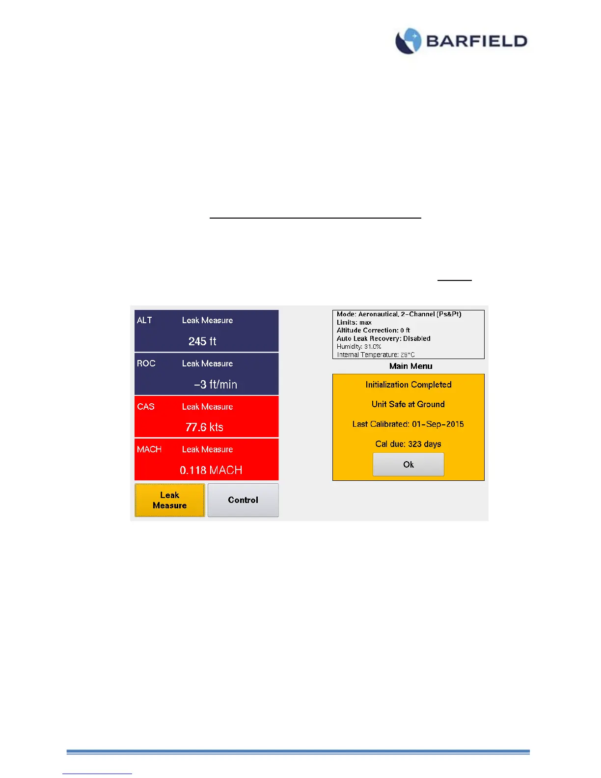
Note: After power ON initialization has completed, the Test Set will remain in Leak
Measure mode with the STATIC (Ps) and PITOT (Pt) ports Vented to ambient
and the displayed message will be:
Figure 47 Initialization Display
C. Leak Measure Mode
The DPS1000 has two modes of operation, Leak Measure and Control. The default
mode of operation for the DPS1000 is Leak Measure mode. At the conclusion of power
ON initialization the Test Set will be placed in the Leak Measure mode.
While in Leak Measure mode the Test Set is continuously measuring / monitoring the
pressure on both the STATIC (Ps) and PITOT (Pt) ports. The display will be continuously
updated (~ 2 times/second) with the latest pressure measurement results. In Leak
Measure mode, the pneumatic pressure pump, vacuum pump and four proportional
control values (PvPs_V, PvPs_P, PvPt_V, PvPt_P, reference DPS1000 Pneumatic
diagram, Appendix C) are off.
When the Display Setup is configured for Aeronautical mode, the DPS1000 has some
additional features and safe guards such as ALR and Leak Test ATP.
While in Leak Measure mode, the ALR “Auto Leak Recover” (if enabled) monitors the
leak rate of ROC and RtCAS. If the rates exceed the values defined under the Limits