3
Pre-threaded
section of
post
1.
2.
3.
4.
5.
Determine where you would like to install the
frame kit. Make sure the posts will be held in
place by a solid structure and if necessary,
reinforce the surface it is attaching to.
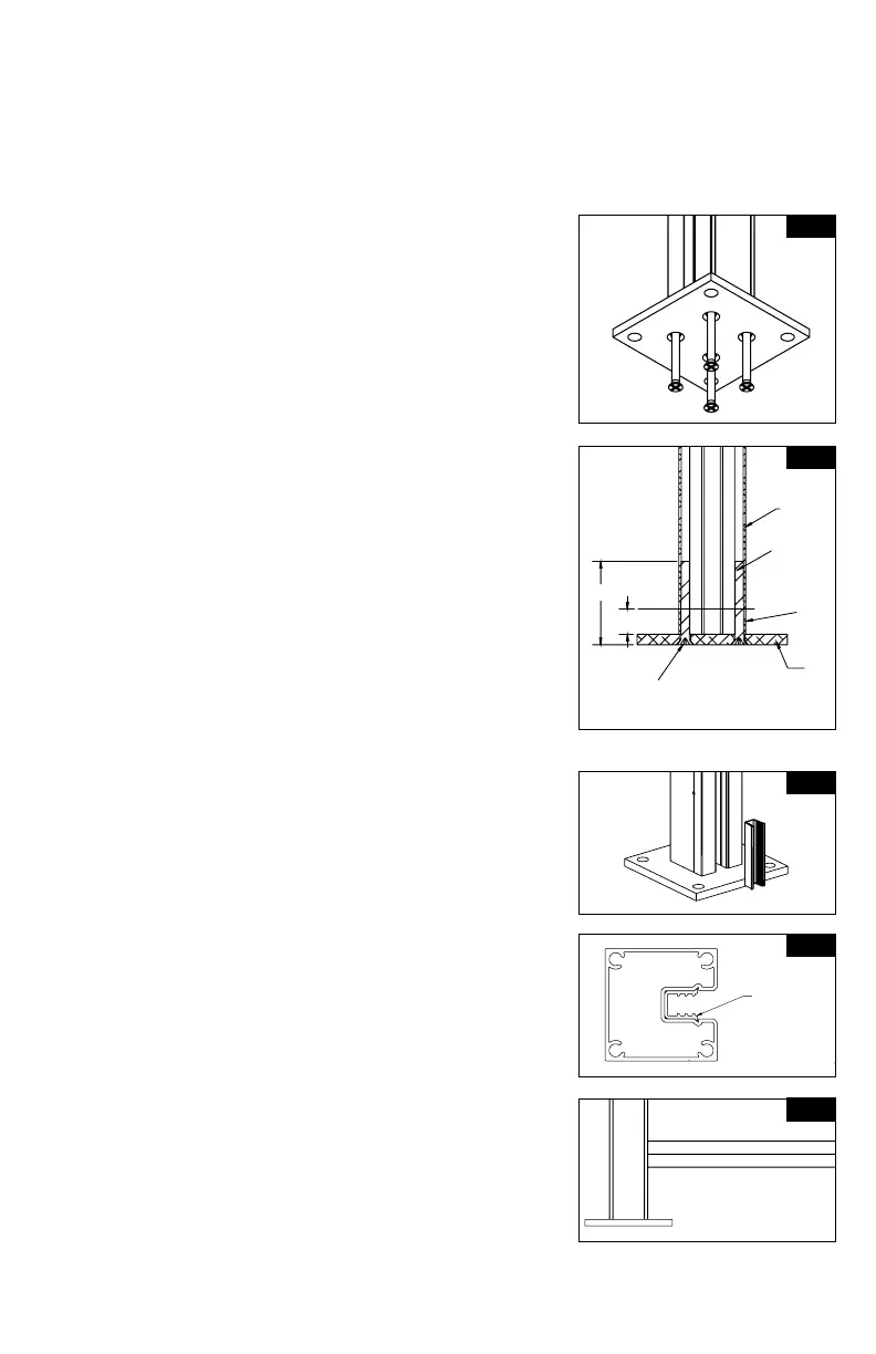
Install base plates to bottom of posts. Locate
bottom post with pre-tapped holes and attach
the bottom plate to that end. Using a #3 Phillips
drive bit, screw base plate to bottom of post
through the (4) screw bosses (Fig. 1). Posts are
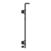
partially threaded on one end of the post (3/4").
While installing screws, you will feel resistance at
the 3/4" mark for a tighter, more secure t. Install
screws until they're ush with the plate (Fig. 2).
TIP:
Drill should be set to low speed when securing
plates to post.
Set rst post in desired location. Use the post
assembly to mark the holes for the surface
mounting plate. Mark and drill holes for
appropriate 3/8" fasteners (fasteners will vary
depending on mounting surface).
Attach post/base assembly to surface using
appropriate 3/8" fasteners.
NOTE:
Keep in mind ceiling clearance if installing
inside. Attaching post/base assembly
to surface may need to wait until end of
installation if full assembly must be tilted for
all 3 panels to be installed properly.
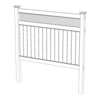
Insert 3" post channel spacer at bottom of post.
Channel should sit on top of the post mounting
plate. (Fig. 3A & 3B). Take bottom rail and insert
into channel or rst post, resting on the spacer
(Fig. 4).
NOTE:
This step is to set distance in between posts.
Repeat step 4 with second post by inserting
the bottom spacer. Take second post and insert
opposite side of bottom rail into the channel of
this post. Be sure rail is fully inserted into the
post. Lock second post into position by repeating
Step 3.
NOTE:
If connecting more than one frame kit
together, line or corner posts are available
(sold separately).
Fig. 1
Fig. 2
Post
2-1/2"
3/4"
1/4-20
Screw
Screw head
should be ush
to the base of
the plate
Base Plate
A
DETAIL A
SCALE 1 : 3
CC
D
SECTION C-C
DETAIL D
SCALE 1 : 1
CHANNEL CORRECTLY
INSTALLED INTO POST
FIG 1
F
DETAIL F
SCALE1 : 3
INSTALL BOTTOM "U" CHANNEL INTO POST.
BOTTOM OF CHANNEL SHOULD SIT ON TOP OF 3" SPACER.
INSTALL SCREW THRU HOLE - USING A PHILLIPS BIT INSTALL SCREW THRU RAIL
A
HH
K
K
J
SECTION H-H
DETAIL J
SCALE 1 : 1
RAIL INSTALLED CORRECTLY
FIG 2
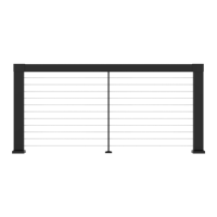
M
SECTION K-K
DETAIL M
SCALE 1 : 1.5
U-CHANNEL
3" PVC CHANNEL
SCREW
TYPICAL 1ST STEP ON ALL SCREENS
INSTALL 3" POST CHANNEL INTO POST - SHOULD SIT ON TOP OF THE POST MOUNTING PLATE.
A
DETAIL A
SCALE 1 : 3
CC
D
SECTION C-C
DETAIL D
SCALE 1 : 1
CHANNEL CORRECTLY
INSTALLED INTO POST
FIG 1
F
DETAIL F
SCALE1 : 3
INSTALL BOTTOM "U" CHANNEL INTO POST.
BOTTOM OF CHANNEL SHOULD SIT ON TOP OF 3" SPACER.
INSTALL SCREW THRU HOLE - USING A PHILLIPS BIT INSTALL SCREW THRU RAIL
A
HH
K
K
J
SECTION H-H
DETAIL J
SCALE 1 : 1
RAIL INSTALLED CORRECTLY
FIG 2
M
SECTION K-K
DETAIL M
SCALE 1 : 1.5
U-CHANNEL
3" PVC CHANNEL
SCREW
TYPICAL 1ST STEP ON ALL SCREENS
INSTALL 3" POST CHANNEL INTO POST - SHOULD SIT ON TOP OF THE POST MOUNTING PLATE.
Fig. 4
Fig. 3A
Fig. 3B
Channel
correctly
installed
into post