AW00123409000 Physical Interface
Basler ace USB 3.0 67
5 Physical Interface
This chapter provides detailed information, such as pinouts and voltage requirements, for the
physical interface on the camera. This information will be especially useful during your initial
design-in process. The chapter also includes information abut the required cables connecting to the
camera.
5.1 General Description of the
Camera Connections
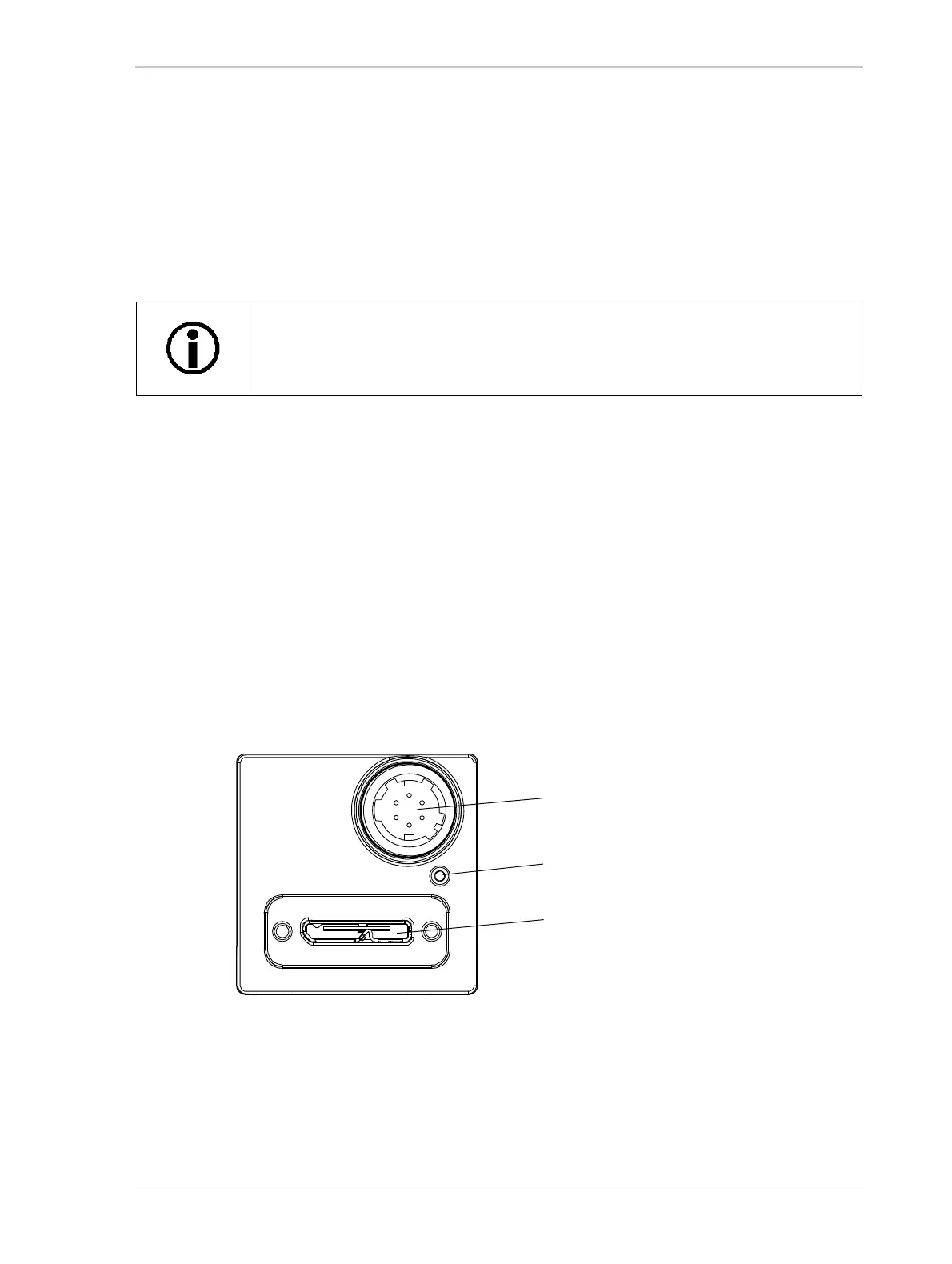
The camera is interfaced to external circuitry via connectors located on the back of the housing:
A 6-pin connector used to provide access to the camera’s I/O lines
A USB 3.0 Micro-B port used to provide a (nominal) 5 Gbit/s SuperSpeed data transfer
connection.
There is also a LED indicator located on the back of the camera.
Figure 38 shows the location of the two connectors and the LED.
Note that Basler recommends specific external components - host adapters,
cables, hubs - for use with Basler ace USB 3.0 cameras. For recommended
external components, see the Basler website: www.baslerweb.com
Fig. 38: Camera Connectors
6-pin Connector (I/O)
Green LED Indicator
USB 3.0 Micro-B Port