SECTION 3 • FUNCTIONAL DESCRIPTION
INTRODUCTION
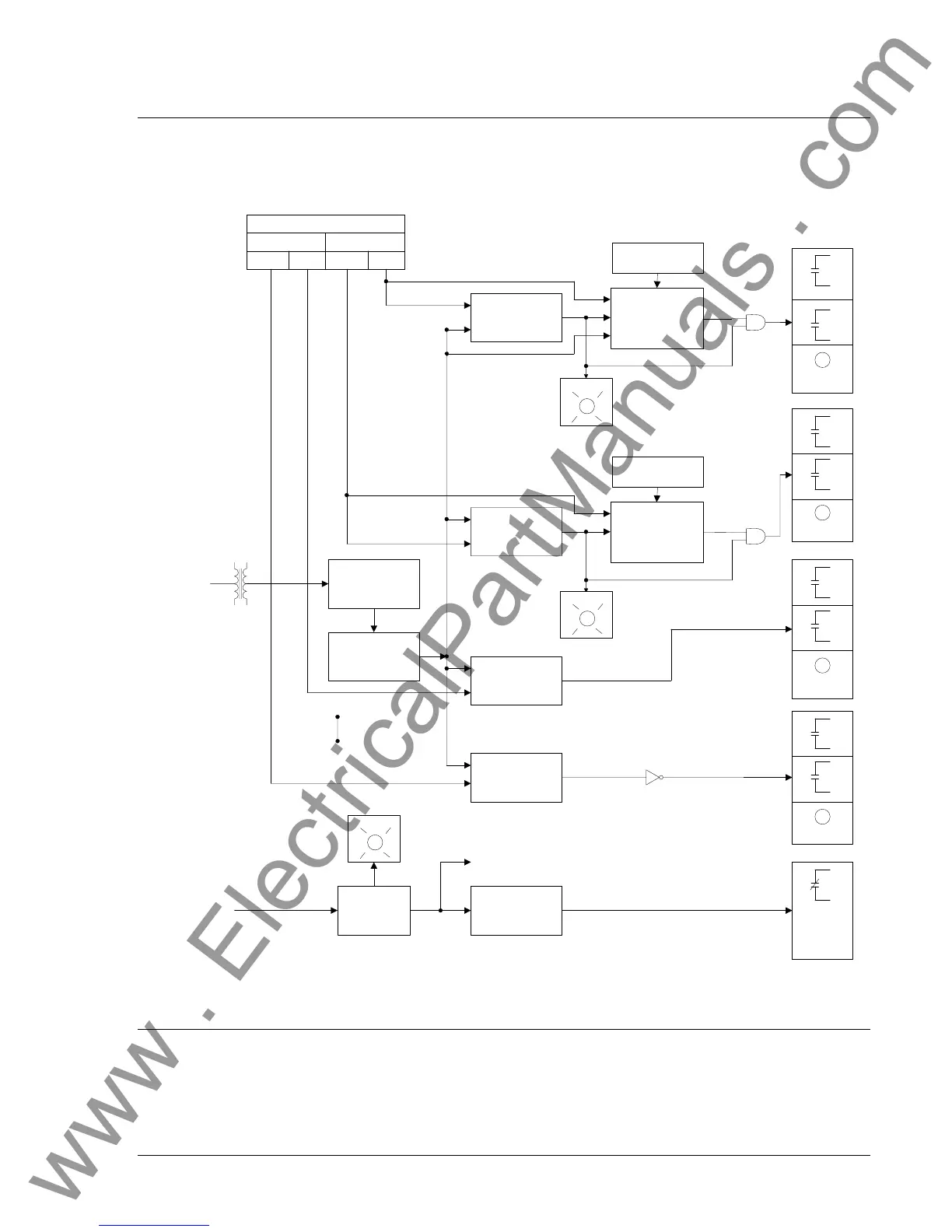
BE1-27, BE1-59, and BE1-27/59 relay functions are illustrated in Figure 3-1 and described in the following
paragraphs.
AUX.
TARGET
AUX.
AUX.
AUX.
POWER
SUPPLY
STATUS
OV TIME
DIAL
OV
TIMER
TIMED
OV
COMPARATOR
OV
PICKUP SETTINGS
INST. TIMED
UNDER OVER
UNDER
OVER
UV TIME
DIAL
UV
TIMER
TIMED
UV
COMPARATOR
UV
INST.
OV
COMPARATOR
INST.
UV
COMPARATOR
POWER
SUPPLY
SENSOR
UV
POWER
SUPPLY
SENSOR
TO INTERNAL
CIRCUITRY
FULL-WAVE
RECTIFIER
LOW-PASS
FILTER
MONITORED
VOLTAGE
OPERATING
POWER
D2354-03
03-11-96
TARGET
TARGET
TARGET
Figure 3-1. Function Block Diagram
SYSTEM VOLTAGES
The BE1-27, BE1-59, and BE1-27/59 relays are available with three sensing input ranges. The 55 to
160V range is intended for use with nominal system voltages of 120V or 69V (120 ÷ √3). The 110 to
320V range is intended for use with nominal system voltages of 240V, 208V (120 x √3) or 277V (480 ÷
√3). The 1 to 40V range is intended for use with a wye/broken delta PT configuration with 120V or 69V
9170600990 Rev H BE1-27/59 Functional Description 3-1
www . ElectricalPartManuals . com