BE1-81 Functional Description
3-2
Power Supply
A variety of power supply options allow a wide range of external voltage inputs for relay operation.
Relay operating power is developed by the low burden, flyback switching design, solid-state power
supply. A nominal plus or minus twelve volts dc is delivered to the internal circuitry. Power supply
inputs are not polarity sensitive. A red LED lights to indicate that the power supply is functioning
properly. The LED circuit is not provided on styles receiving operating power from the sensing input.
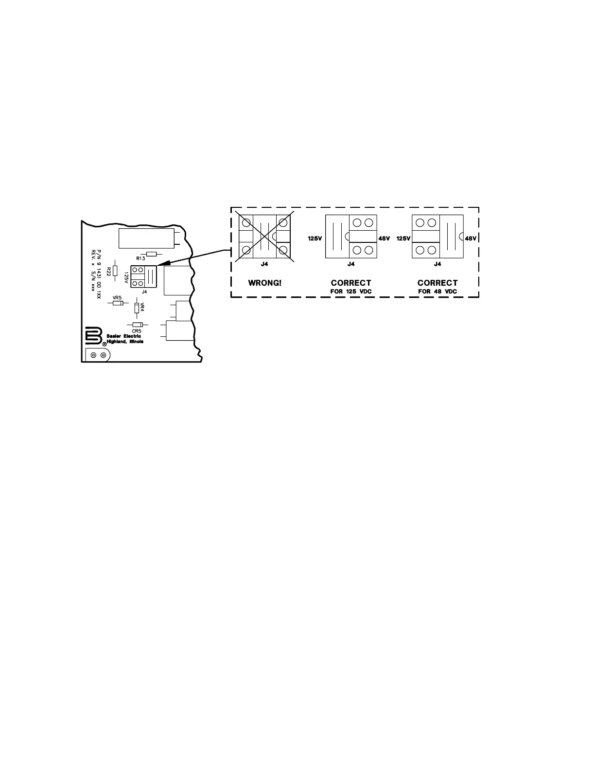
Type W power supplies use a field adjustable link (J4) to select the appropriate input voltage (either 48
Vdc or 125 Vdc). Selection is accomplished by placing the link into the desired position (refer to Figure
3-2). This link is factory pre-set for 125 Vdc.
Figure 3-2. J4 Link Positioning
Power Supply Status Contacts
Power supply voltages are monitored on the mother board. Normal supply voltage causes the power
supply status relay to be continually energized. However, if at any time the voltage falls below
requirements, the relay drops out, and closes the normally closed contacts.
Voltage Inhibit Circuit
This circuit prevents the relay from tripping because of transient underfrequency conditions associated
with equipment startup. It inhibits sensing of underfrequency conditions by the synchronizer circuit and
output circuitry until the input sensing voltage is greater than 80 Vac.
Input Conditioning Circuit
The input conditioning circuit converts the sensing voltage to a squarewave whose transitions
correspond to the zero crossings of the input waveform. The resulting squarewave (after further
shaping) is applied to the synchronizer circuit.
Crystal Reference Oscillator
This four megahertz, crystal-controlled oscillator provides an accurate reference for the synchronizer
circuit and the frequency reference circuit.