BE1-81 Installation
4-13
NOTE
Be sure the relay case is hard-wired to earth ground with no smaller than 12 AWG
copper wire attached to the ground terminal on the rear of the relay case. When the
relay is configured in a system with other protective devices, it is recommended to use
a separate lead to the ground bus from each relay.
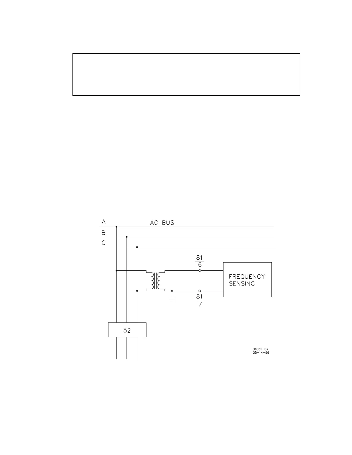
CONNECTIONS
Incorrect wiring may result in damage to the relay. Except as noted previously, connections should be
made with minimum wire size of 14 AWG. Typical AC circuit connections are shown in Figure 4-13, and
typical control circuit connections in Figure 4-14. Internal connections are shown in Figures 4-15 and 4-
16.
Terminals 3 and 4 are external relay power supply voltage inputs and are not polarity sensitive. When
the sensing input power supply (Option 1-2) is specified, the power supply is wired directly from the
sensing input terminals by the factory. Terminals 6 and 7 are the frequency sensing inputs.
Figure 4-13. AC Sensing Input Connections