Installation Guide
Basler IP Camera 7
LanguageLanguageLanguageLanguageLanguageLanguageLanguageLanguage
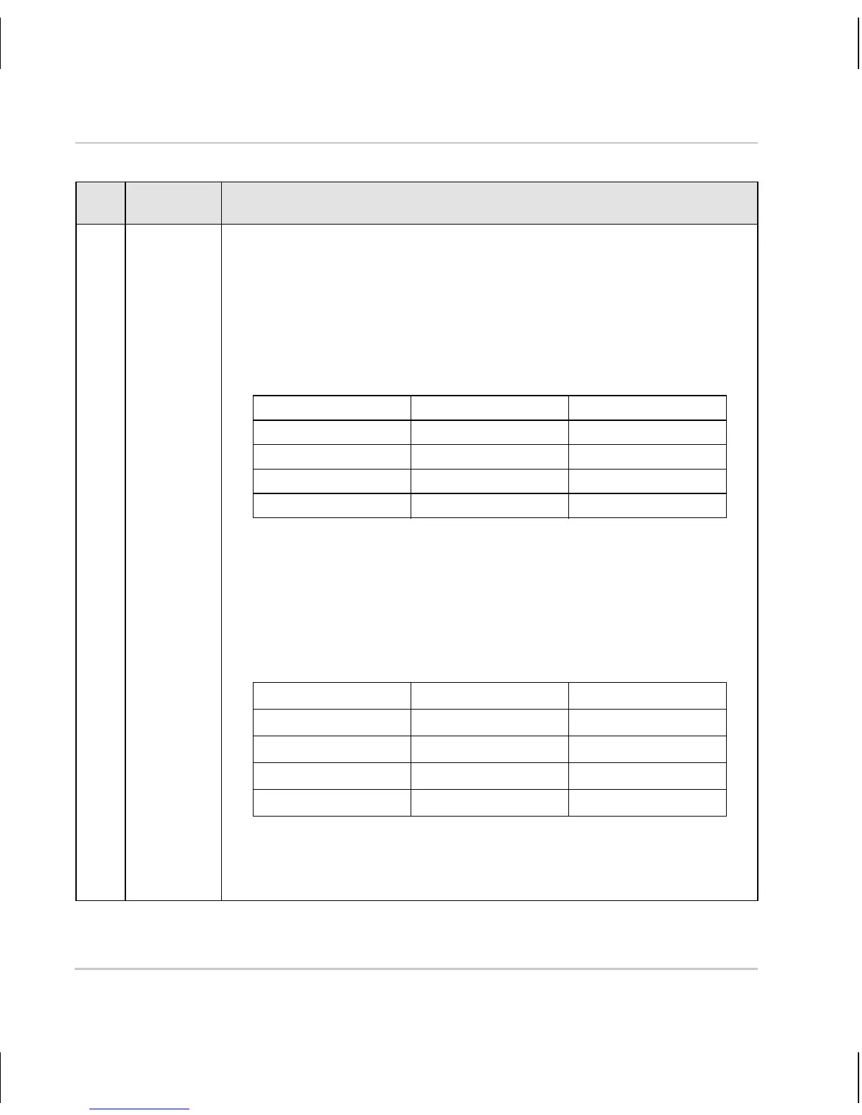
3 Input Normally, the input is connected to ground via a switch as shown
in Figure 3 on page 10. As shown in the table below, the input will
be detected by the camera as active or inactive depending on
whether the switch is open or closed and whether the input mode
is set to normal or inverted.
See the camera User’s Manual for more information about setting
the input mode.
Switch Condition Input Mode Input Detected As
Open Normal Inactive
Closed Normal Active
Open Inverted Active
Closed Inverted Inactive
As an alternative, voltage from a device can be applied directly to
the input. As shown in Figure 4 on page 11, the voltage should be
applied directly to the input and not through a switch.
As shown in the table below, the input will be detected by the
camera as active or inactive depending on the voltage level
applied and whether the input mode is set to normal or inverted.
Voltage Applied Input Mode Input Detected As
0 to +2.6 VDC Normal Active
+5.7 to +24.0 VDC Normal Inactive
0 to +2.6 VDC Inverted Inactive
+5.7 to +24.0 VDC Inverted Active
The area between +2.6 and +5.7 VDC is a transition zone and
should be avoided. The voltage applied to the input must not
exceed +24 VDC.
Pin Function Description
Table 2: Camera Pinout
 Loading...
