Installation Guide
8 Basler IP Camera
4 Output The output employs an open collector transistor connected to
ground as shown in Figure 3 on page 10. As shown below, the
output will or will not be connected to ground via the transistor
depending on the state of the output and whether the output is set
for the normal or the inverted mode.
See the camera User’s Manual for more information about setting
the output mode.
Note: If the output has been set to the inverted mode and you
restart the camera or you power it off and back on, the output will
be in the normal mode during the camera bootup process and will
return to the inverted mode once the bootup process is complete.
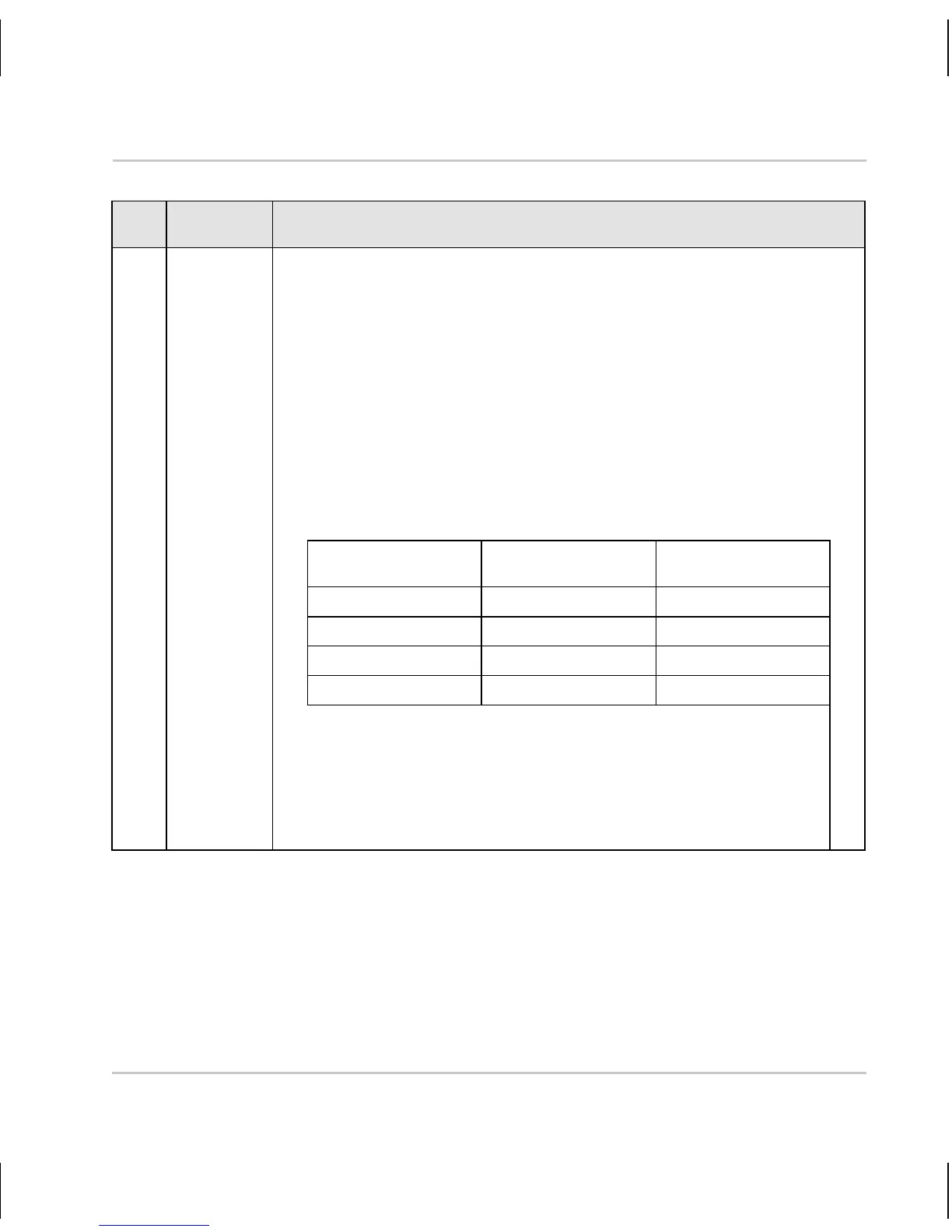
Output State Output Mode Output Connected
to Ground
Inactive Normal No
Active Normal Yes
Inactive Inverted Yes
Active Inverted No
The maximum load is 100 mA and the maximum voltage is
+24 VDC.
If an inductive load such as a relay is used with the output, a
diode must be connected in parallel with the load as shown in
Figure 3.
Pin Function Description
Table 2: Camera Pinout
 Loading...
