3-8 9469300994
Typical Applications DGC-2020HD
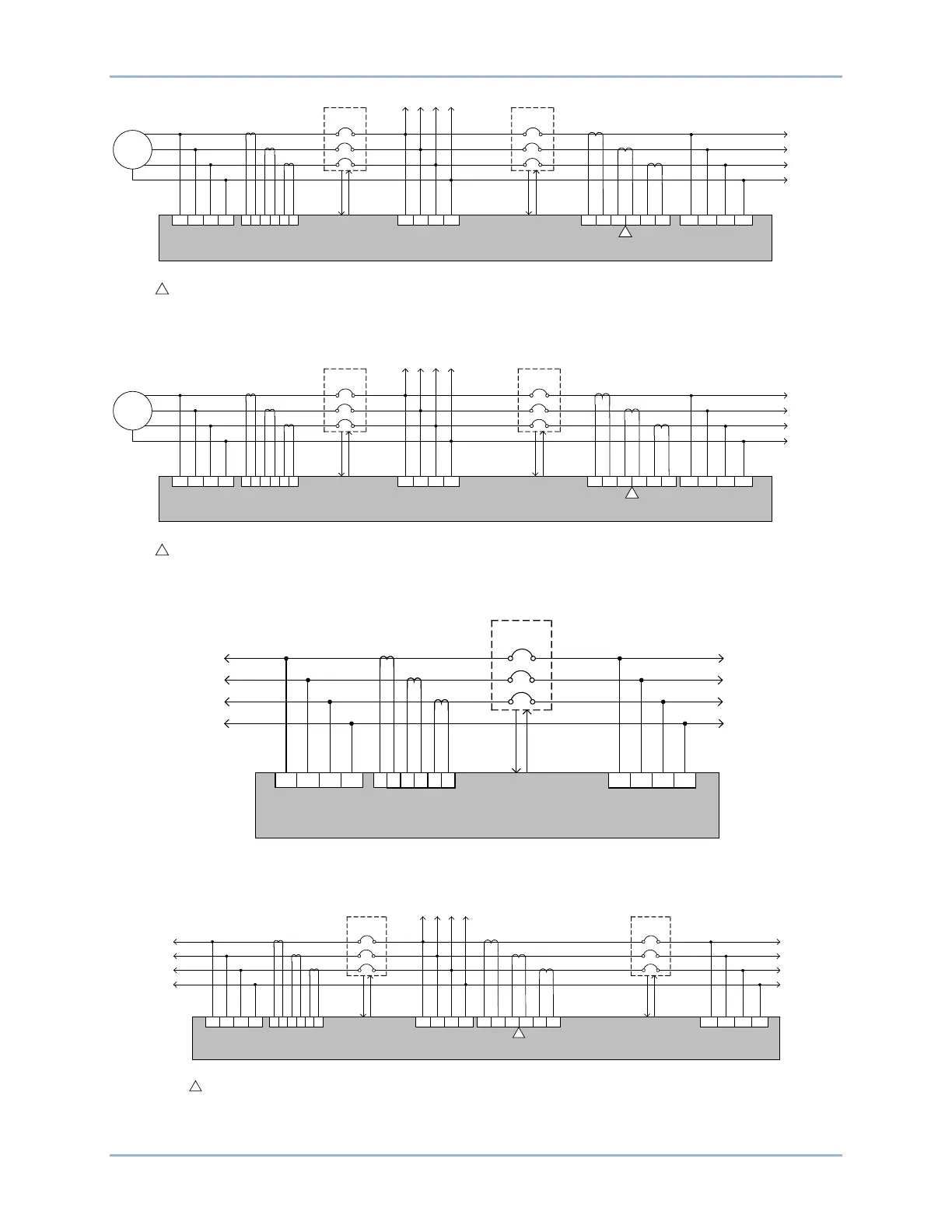
Figure 3-15. Generator and Group Breaker Control to Segmented System Connections
Figure 3-16. Generator and Tie Breaker Control Connections
Figure 3-17. Tie Breaker Control Connections
Figure 3-18. Dual Tie Breaker Control Connections
Generator
L1
L2
L3
Generator Bus
Generator
Bus Metering
86 88
90
DGC-2020HD
91
N
Generator
Breaker
Group
Bus
Generator
Breaker
Control Output
93 95 97
Group Bus
Metering
1
2 3
4 5 6
Generator
Breaker
Status
98
Bus 1
Notes:
An auxiliary CT is only required if group breaker power measurement is desired. Group breaker power measurement is required for
the group breaker Zero Power Transfer function.
1
Group Breaker
Control Output
Group
Breaker
Status
P0081-66
Group
Breaker
To other generators
Segmented
System Bus
Segmented System
Bus Metering
To Segmented
System
1
11 129 107 8
100
101 103 104
Bus 2
A
B
C
N
Generator
L1
L2
L3
Generator Bus
Generator
Bus Metering
86 88 90
DGC-2020HD
91
N
Generator
Breaker
Segmented
System Bus “B”
Generator
Breaker
Control Output
93 95 97
Segmented
System Bus
“B” Metering
1
2
3
4 5
6
Generator
Breaker
Status
98
Bus 1
Notes:
Auxiliary CTs are only required if tie breaker power measurement is desired. Tie breaker power measurement is required for the
Zero Power Transfer function across the tie breaker.
1
Tie Breaker
Control Output
Tie
Breaker
Status
P0081-67
Tie Breaker
To Segmented System “B”
Segmented
System Bus “C”
Segmented System
Bus “C” Metering
To Segmented
System “C”
1
11 129 107 8
100 101 103
104
Bus 2
A
B
C
N
A
B
C
P0081-68
86 88 90
DGC-2020HD
91
N
Tie Breaker
Segmented
System Bus “B”
Tie Breaker
Control Output
93 95 97
Segmented System
Bus “B” Metering
1
2 3
4 5 6
Tie
Breaker
Status
98
Bus 1
To Segmented
System “B”
A
B
C
N
To Segmented
System “A”
Segmented
System Bus “A”
Segmented System
Bus “A” Metering
A
B
C
86 88 90
DGC-2020HD
91
N
Tie Breaker
1
Tie Breaker 1
Control Output
93 95 97
1
2 3 4 5 6
Tie
Breaker 1
Status
98
Bus 1
Notes:
Auxiliary CTs are only required if Tie Breaker 2 power measurement is desired. Tie Breaker
2 power measurement is required for
the Zero Power Transfer function across Tie Breaker 2.
1
Tie Breaker 2
Control Output
Tie
Breaker 2
Status
P0081-69
Tie Breaker
2
Segmented
System Bus “C”
Segmented System
Bus “C” Metering
To Segmented
System “C”
1
11 129 107
8
100 101 103
104
Bus 2
A
B
C
N
Segmented
System Bus “B”
Segmented
System Bus “A”
Segmented System
Bus “B” Metering
Segmented System
Bus “A” Metering
To Segmented System “B”
To Segmented
System “A”