0 1020304050
10
20
30
40
50
60
70
80
90
100
'
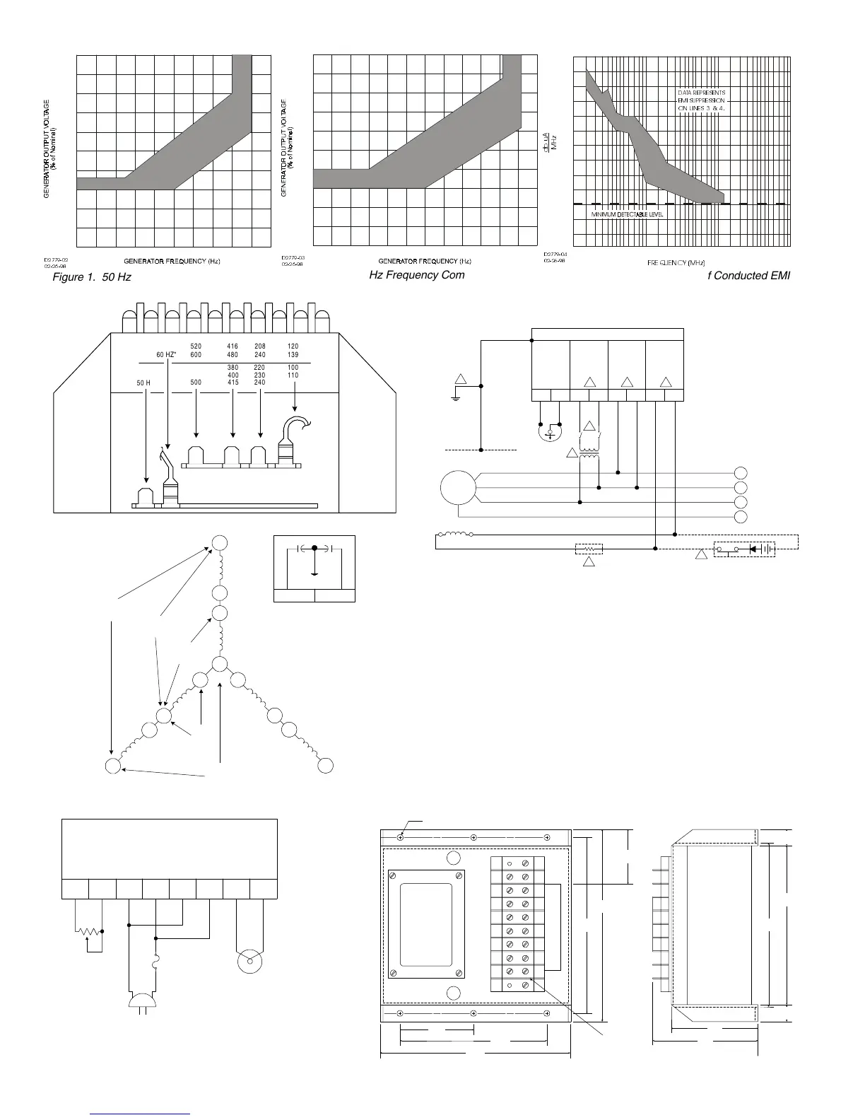
Figure 1. 50 Hz Frequency Compensation
0 10203040 60
10
20
30
40
50
60
70
80
90
100
'
50
Figure 2. 60 Hz Frequency Compensation
10
20
30
40
50
60
70
80
90
100
130
120
110
0
0.010.01 50.0 100.00.05 1.0 5.0 10.0
'
)5(48(1&< 0+]
GE X$
0+]
'$7$ 5(35(6(176
(0, 68335(66,21
21 /,1(6
Figure 3. Typical Suppression of Conducted EMI
60 HZ* 600
520
240
208
480
416
139
120
500 415
400
380
240
230
220
110
100
50 HZ*
D2779-06
02-27-98
Figure 4. Sensing Transformer Connections
KR-FX/KR-FFX VOLTAGE REGULATOR
VOLT
ADJ.
INPUT
POWER
SENSING
VOLTAGE
FIELD
POWER
500
OHMS
1 2 3
67 34E1E3F+F-
6
4
1
GENERATOR CHASSIS
CW
GENERATOR
A
B
C
N
+-
EXCITER FIELD
3
5
D2779-07
06-19-00
Figure 5. Interconnection Diagram (Typical)
T1
T4
T7
T10
T12
T11
T9
T6
T3
T8
T5
T2
240 VAC
OR
277 VAC
120 VAC
OR
139 VAC
208 VAC
OR
240 VAC
318 VAC
OR
366 VAC
416 VAC
OR
480 VAC
34
KR-FX/FFX
D2779-08
02-27-98
Figure 6. Ungrounded Neutral Generator System (Typical)
2.015
(51.18)
7.125
(180.97)
5.50
(139.70)
2.75
(69.85)
7.10
(180.34)
0.218 (5.537) DIA., 6 PLACES
6.50
(165.10)
8 TERMINALS
WITH 5-40
SCREWS SPACED
ON .437 (9. 5 25)
CENTERS
NOTE: NUMBERS IN PARENTHESIS ARE IN MILLIMETERS.
D2779-09
03-03-98
3.937
(99.99)
3.25
(82.55)
1.00
(25.4)
5.25
(133.35)
5.10
(129.5)
1.00
(25.4)
Figure 7. KR Regulator, Outline Drawing
KR-FX OR KR-FFX VOLTAGE REGULATOR
6 7 3 4 E1 E3 F+ F-
LIGHT
BULB
POWER
SOURCE
120 VOLTS
60 HERTZ
EXTERNAL
VOLTAGE
ADJUST
RHEOSTAT
D2779-10
10-16-98
(IF GLASS TYPE FUSE IS USED
ENCLOSE FOR SAFETY.)
Figure 8. Functional Test Setup
NOTES
:
1. Power matching transformer is required if appropriate input voltage is not available at
generator terminals. If field or flashing circuit is grounded, an isolation transformer is
also required.
2. Internal sensing transformer is provided with taps. It is shipped connected to the 120
Volt tap. If voltage other than 120 V is required, connect wire to applicable tap.
3. The exciter field dc resistance must be at least that listed in the
Specifications
. If not,
a series resistor must be added so that the total resistance is at least this value.
4. Shutdown switch allows removal of field excitation. If switch is not used, a temporary
switch should be installed during initial operation.
5. The regulator contains an internal relay for voltage buildup. If flashing is required,
refer to
Field Flashing
. If permanent field flashing is desired, connect as shown and
limit flashing current to <50% of no-load field current. Diode rating: 15 A, 600 PIV.
6. Regulator and generator must be grounded. This is pertinent for EMI suppression. If
ungrounded, the KR regulator will be electrically hot.
www . ElectricalPartManuals . com
 Loading...


