2-2 BE1-51 Controls and Indicators 9137200997 Rev D
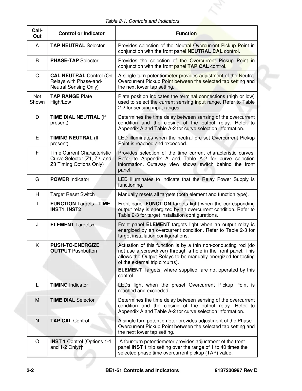
Table 2-1. Controls and Indicators
Call-
Out
Control or Indicator Function
A TAP NEUTRAL Selector Provides selection of the Neutral Overcurrent Pickup Point in
conjunction with the front panel NEUTRAL CAL control.
B PHASE-TAP Selector Provides the selection of the Overcurrent Pickup Point in
conjunction with the front panel TAP CAL control.
C CAL NEUTRAL Control (On
Relays with Phase-and-
Neutral Sensing Only)
A single turn potentiometer provides adjustment of the Neutral
Overcurrent Pickup Point between the selected tap setting and
the next lower tap setting.
Not
Shown
TAP RANGE Plate
High/Low
Plate position indicates the terminal connections (high or low)
used to select the current sensing input range. Refer to Table
2-2 for sensing input ranges.
D TIME DIAL NEUTRAL (If
present)
Determines the time delay between sensing of the overcurrent
condition and the closing of the output relay. Refer to
Appendix A and Table A-2 for curve selection information.
E TIMING NEUTRAL (If
present)
LED illuminates when the neutral pre-set Overcurrent Pickup
Point is reached and exceeded.
F Time Current Characteristic
Curve Selector (Z1, Z2, and
Z3 Timing Options Only)
Provides selection of the time current characteristic curves.
Refer to Appendix A and Table A-2 for curve selection
information. Cutaway view shows switch behind the front
panel.
G POWER Indicator LED illuminates to indicate that the Relay Power Supply is
functioning.
H Target Reset Switch Manually resets all targets (both element and function type).
I FUNCTION Targets - TIME,
INST1, INST2
Front panel FUNCTION targets light when the corresponding
output relay is energized by an overcurrent condition. Refer to
Table 2-3 for target installation configurations.
J
ELEMENT Targets∗
Front panel ELEMENT targets light when an output relay is
energized by an overcurrent condition. Refer to Table 2-3 for
target installation configurations.
K
PUSH-TO-ENERGIZE
OUTPUT Pushbutton
Actuation of this function is by a thin non-conducting rod (do
not use a screwdriver) through a hole in the front panel. This
allows the Output Relays to be manually energized for testing
of the external trip circuit(s).
ELEMENT Targets, where supplied, are not operated by this
control.
L TIMING Indicator LEDs light when the preset Overcurrent Pickup Point is
reached and exceeded.
M TIME DIAL Selector Determines the time delay between sensing of the overcurrent
condition and the closing of the output relay. Refer to
Appendix A and Table A-2 for curve selection information.
N TAP CAL Control A single turn potentiometer provides adjustment of the Phase
Overcurrent Pickup Point between the selected tap setting and
the next lower tap setting.
O INST 1 Control (Options 1-1
and 1-2 Only)†
A four-turn potentiometer provides adjustment of the front
panel INST 1 trip setting over the range of 1 to 40 times the
selected phase time overcurrent pickup (TAP) value.
Courtesy of NationalSwitchgear.com
 Loading...


