9137200997 Rev D BE1-51 Installation 4-7
CONNECTIONS
Be sure to check the model and style number of a relay before connecting and energizing the relay.
Incorrect wiring may result in damage to the relay. Except where noted, connections should be made with
wire no smaller than 14 AWG.
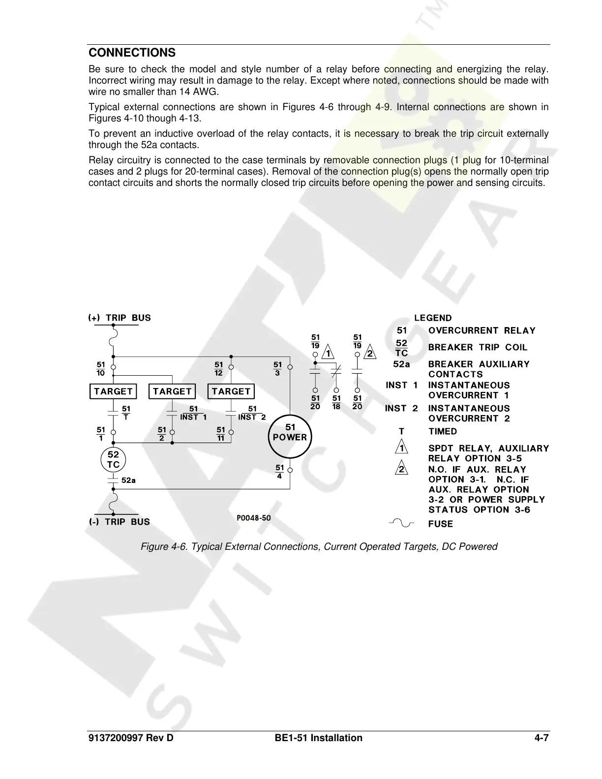
Typical external connections are shown in Figures 4-6 through 4-9. Internal connections are shown in
Figures 4-10 though 4-13.
To prevent an inductive overload of the relay contacts, it is necessary to break the trip circuit externally
through the 52a contacts.
Relay circuitry is connected to the case terminals by removable connection plugs (1 plug for 10-terminal
cases and 2 plugs for 20-terminal cases). Removal of the connection plug(s) opens the normally open trip
contact circuits and shorts the normally closed trip circuits before opening the power and sensing circuits.
Figure 4-6. Typical External Connections, Current Operated Targets, DC Powered
Courtesy of NationalSwitchgear.com
 Loading...


