Page 7;&(%$*4.8"4,7%<'*#$"&8#=%/7*,#*%4,77%>?@@@?@AA?BCDC1Item 58339
EF;6GHIJ6KFGLIMNFLMG6MFMO6 E6GPJ
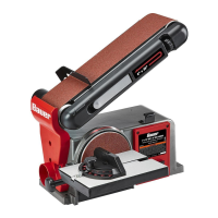
F##*5+7V0N&'8$"83
N&'8$"83%E,89*(
1. Select a workbench or mounting location that is
able to support the weight of the Sander, plus
any additional weight placed on it during use.
2. Use the mounting bolt holes provided in the Base
to mount the Sander to the mounting location
before use. Mounting hardware not included.
L8#$,77%E,89"83%U"#4%,89%R',(9
1. Wipe down the Backing Disc with
denatured alcohol to remove any
residue and ensure a secure bond.
2. Remove backing from Sanding Disc (7).
3. Align perimeter of Sanding Disc over
the Backing Disc and press Sanding
Disc firmly onto the Backing Disc.
4. Position Disc Guard (6) against lower
1/3 of Sanding Disc, aligning slots in
Guard with holes in Base. Fasten securely
XVLQJWZR6W[10 Screws (5) and
Star Washers (4). Refer to Figure A.
E,89"83%
U"#4
Q,#.*(
E4(*)
U"#4%
R',(9
S,4b"83%
U"#4
;"3'(*%F
N&'8$"83%Q&(b%G,+7*
1. Hold the Work Table (35) in a horizontal position and
insert the pivot pin on the Work Table Support into
the pivot hole on the Sander Base. Hold in place.
2. Insert the Work Table Lock Knob (63)
with Washer (32) into the threaded hole
and tighten. Refer to Figure B.
3. Adjust the Table so the edge is a maximum
of 1/16 inch from the Sanding Disc.
Q&(b%G,+7*%Q&(b%G,+7*%
E'//&($E'//&($
Q&(b%
G,+7*
Q,#.*(
Q&(b%G,+7*%
T&4b%^8&+%
J"W&$%
.&7*%
;"3'(*%S
N&'8$"83%;*84*
1. The Fence (60) fits across the top of the
Sanding Belt to prevent workpiece from
moving to the rear when sanding.
2. Align two holes on the Fence with two Holes
on the Belt Support Assembly (59).
3. Secure Fence in place using two M8[16 Set
Screws and Washers (52). Refer to Figure C.
QFKMLMRc%%GI%JK6!6MG%E6KLIPE%LMaPKH-%
Adjust Fence height to avoid contact with
Sanding Belt and allow free Belt movement.
;"3'(*%O
S*7$%E'//&($%S*7$%E'//&($%
F##*5+7VF##*5+7V
;*84*
E*$%
E4(*)