Manual for BAUER RAINSTAR A1, A2
25
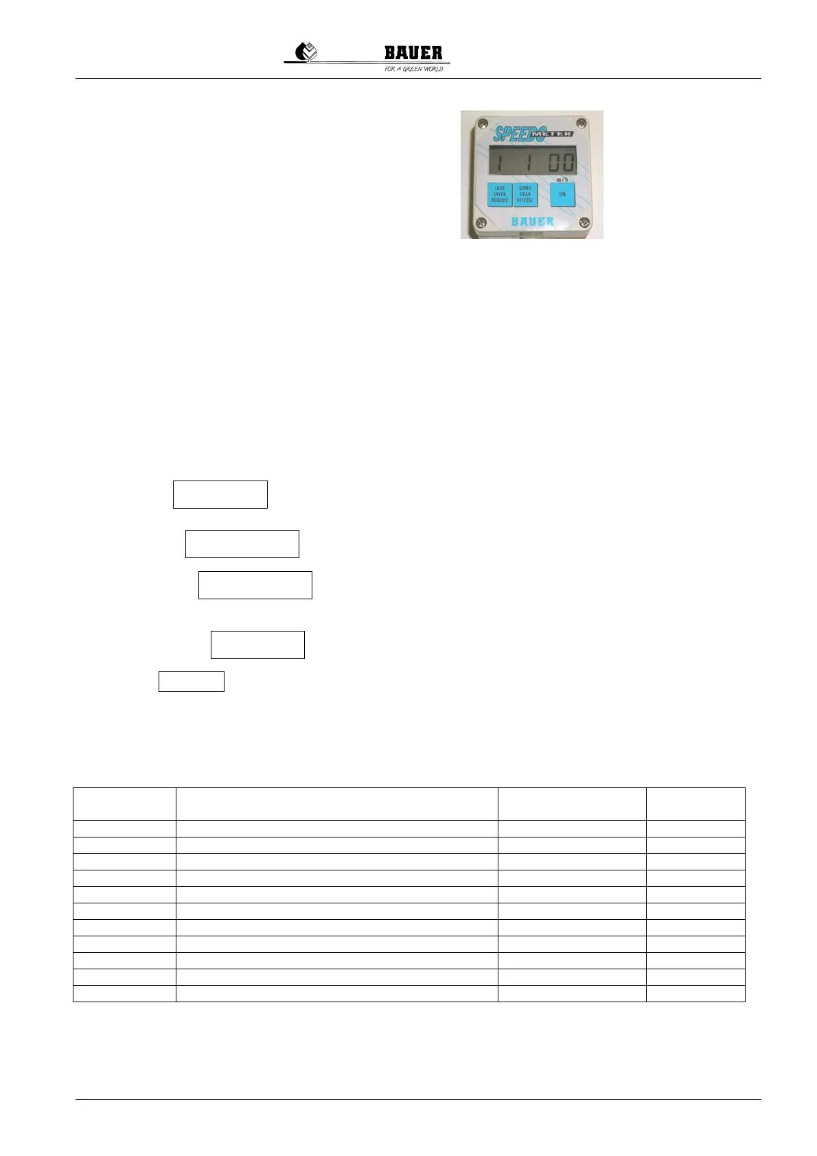
16 SPEEDOMETER (Option)
Operating Instructions SPEEDOMETER
Description:
This speedometer allows to read the sprinkler's retraction speed comfortably on the big LCD display. For an
exact indication of the retraction speed in m/h, the existing PE-pipe layer must be selected with the keyboard.
The exact retraction speed is calculated via measuring pulses in the electronic box and it is based on the
selected operating data. These measuring pulses are taken over contactless with magnetic sensors at the gear
input. The machine data remain saved permanently in the electronics and they need to be entered only once
during assembly. If necessary these data can be reprogrammed to other machine types any time.
Technical data:
Power supply: 9 Volt battery (type PP3) – holds for 1.000 speed measuring’s of 4 minutes each
Box: made of synthetic material, dimensioned 82 mm x 80 mm x 50 mm
Sensor: permanent magnetic insert and magnetic sensor on gear input shaft
Operating steps:
1. Press the . – The display is switched ON.
Important note! – The display is switched off automatically after 4 minutes.
2. Press the until the existing pipe layer is on display.
3. Press the until the gear used is on display.
4. The retraction speed in m/h is displayed immediately on the right side of the display.
5. As long as the is pressed, the revolutions per minute at the gear input are on display.
6. Blinking
Lo on the display indicates low battery voltage (less than 7.5 Volt). – Replace the battery!
Programming of machine data:
Factory setting of the speedometer is based on the machine data according to the below table. For an exact
and appropriate indication of the retraction speed of your machine, its specific parameter data must be entered.
Constant no.
Description
Possible setting
range
Standard
setting
1 Pulses per meter in gear 1 100-4000 1000
2 Pulses per meter in gear 2 100-4000 900
3 Pulses per meter in gear 3 100-4000 800
4 Pulses per meter in gear 3 100-4000 700
5 Pulses per meter in gear 3 100-4000 600
6 Pulses per meter in gear 3 100-4000 500
7 Reel core diameter (in mm) 500-3000 1400
8 PE-pipe diameter (in mm) 40-200 100
9 Number of layers 1-9 5
A Number of gears 1-6 3
b By pressing the "ON" key, the data are saved
For the specific machine data of the machine types, see chart sheets 1 and 2.
ON key
LAYER key
GEAR key
ON key