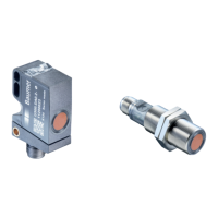
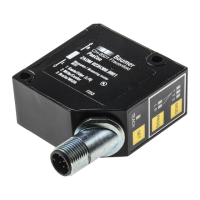
UNDK 20P6914/S35A
10141538
1/2
Ultraschall-Sensoren
Ultrasonic sensors
Détecteurs à ultrasons
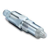
Näherungsschalter
Proximity sensor
Détecteur de proximité
Canada
Baumer Inc.
CA-Burlington, ON L7M 4B9
Phone +1 (1)905 335-8444
China
Baumer (China) Co., Ltd.
CN-201612 Shanghai
Phone +86 (0)21 6768 7095
Denmark
Baumer A/S
DK-8210 Aarhus V
Phone: +45 (0)8931 7611
France
Baumer SAS
FR-74250 Fillinges
Phone +33 (0)450 392 466
Germany
Baumer GmbH
DE-61169 Friedberg
Phone +49 (0)6031 60 07 0
India
Baumer India Private Limited
IN-411058 Pune
Phone +91 20 66292400
Italy
Baumer Italia S.r.l.
IT-20090 Assago, MI
Phone +39 (0)2 45 70 60 65
Singapore
Baumer (Singapore) Pte. Ltd.
SG-339412 Singapore
Phone +65 6396 4131
Sweden
Baumer A/S
SE-56133 Huskvarna
Phone +46 (0)36 13 94 30
Switzerland
Baumer Electric AG
CH-8501 Frauenfeld
Phone +41 (0)52 728 1313
United Kingdom
Baumer Ltd.
GB-Watchfield, Swindon, SN6 8TZ
Phone +44 (0)1793 783 839
USA
Baumer Ltd.
US-Southington, CT 06489
Phone +1 (1)860 621-2121
www.baumer.com/worldwide
Baumer Electric AG · CH-8501 Frauenfeld
Phone +41 (0)52 728 1122 · Fax +41 (0)52 728 1144
Abmessungen
Dimensions
Dimensions
42
6,5
9,5
3,2
14
M8 x 1
5,7
11,8
15
LEDTeach-in
20
29,5
• Alle Masse in mm
• All dimensions in mm
• Toutes les dimensions en mm
Elektrischer Anschluss
Connection diagrams
Schéma de raccordement
PNP Schliesser (NO)
PNP make function (NO)
PNP à fermeture (NO)
0 V
PNP
WH (2)
BU (3)
BN (1)
BK (4)
Z
+VS
output
control/Teach-in
BN = Braun/brown/brun
BK = Schwarz/black/noir
BU = Blau/blue/bleu
WH = Weiss/white/blanc
• Vor dem Anschliessen des Sensors die Anlage spannungsfrei schalten
• Disconnect power before connecting the sensor
• Mettre l’installation hors tension avant le raccordement du détecteur
Anschlussbelegung
Pin assignment
Raccordement
1 / +VS
3 / 0 V
4 / Output
2 / cont/Teach-In
Bedienungsanleitung
Operating instructions
Notice d'utilisation
Einstellung Schaltpunkt Sde
Teach-in Verriegelung
Teach-in locking
Verrouillage du Teach-in
respectively after the end of the last Teach-in process.
5 min. nach jedem Power-up,
5 min. after every power-up, 5min.après chaque mise sous
bzw. nach dem Ende des letzten Teach-in Vorgangs.
tension resp. après fin du dernier processus Teach-in.
Sensor in die Werkseinstellung zurücksetzten
Teach-in-Taste ca. 2s drücken oder externen Teach-
in-Anschluss mit +Vs verbinden bis die LED grün
1. Den Sensor in den Einstellmodus bringen:
blinkt. Taste loslassen bzw. die Verbindung öffnen.
2. Die LED blinkt grün. Das Objekt an die gewünschte
Bereichsgrenze bringen und die Teach-in-Taste kurz
drücken oder den externen Teach-in-Anschluss kurz
mit +Vs verbinden.
Wird die Teach-in-Taste länger als 6s gedrückt oder der
externe Teach-in-Anschluss mit +Vs verbunden, wird
der Sensor in die Werkseinstellung zurückgesetzt. Der
Sensor zeigt dies durch schnelles Blinken der grünen
3. Bestätigung des erfolgreichen Teach-Vorgangs durch
Leuchten der grünen LED für 2s.
Adjustment switching point Sde
Resetting to original factory settings
Press the Teach-in button or connect the white
Teach-in wire to +Vs for approx. 2secs until the LED
1. Adjustment mode:
flashes green. Release button or disconnect
2. LED flashes green. Place the target at the required
scanning range and press the Teach-in button or
connect the external white Teach-in wire shortly
3. Successful completion of Teach-in procedure is
confirmed by LED being "on" for approx. 2secs.
Holding the button down or connecting the white
Teach-in wire to +Vs for > 6secs, will automatically
restore the original factory setting. Fast flashing of
the green LED indicates successful completion
Ajustage du point de commutation Sde
Réinitialisation des fonctions originales
Presser le bouton Teach-in ou connecter le Teach-in
externe avec +Vs pendant environ 2 secondes
1. Ajustage:
jusqu'à ce que la LED vert clignote.
2. LED clignote en vert. Placer I'objet à détecter à la
distance désirée et presser le bouton Teach-in ou
connecter briévement le Teach-in externe (WH)
avec +Vs.
3. La validation de la procédure Teach-in est confirmée
par I'état de fonctionnement de la LED pendant
environ 2 secondes.
Maintenir le bouton ou connecter le Teach-in externe
avec +Vs pendant > 6 secondes, réinitialisera
automatiquement les fonctions originales. Le
clignotement rapide de la LEDs vert indique la validation
LED an.
Teach-in wire.
to +Vs.
of the resetting.
Relâcher le bouton ou déconnecter le Teach-in externe.
de la réinitialisation.