Do you have a question about the Baumer OX100 and is the answer not in the manual?
Explains the manual's purpose and structure, including warnings and labels.
Covers manufacturer liability, scope of delivery, and sensor identification details.
Defines qualified personnel and covers general safety, installation, and disposal guidelines.
States the product is a Class 1 Laser Product, complying with relevant safety standards.
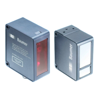
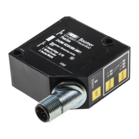
Details sensor structure, triangulation principle, and core measurement functions.
Explains the measurement cycle and factors affecting its speed.
Describes alignment surfaces and the sensor's operational measurement field.
Outlines web interface capabilities, layout components, and sensor LED indicators.
Details Modbus RTU, IO-Link, and external triggering for data communication.
Provides guidelines for proper handling during transport, inspection, and storage.
Covers sensor mounting, alignment, and electrical connection procedures.
Guides on connecting the sensor to a PC and identifying its IP address.
Details configuration steps for Modbus RTU RS485 and IO-Link interfaces.
Explains using Monitoring mode for data visualization and saving data to CSV.
Introduces settings for signal chain, camera adjustments, and visualization views.
Guides on adjusting internal resolution and optimizing exposure time for performance.
Explains trigger modes, sensor alignment, and mounting assistant functions.
Explains compensating mounting angles using Flex Mount and related setup procedures.
Covers tool allocation, position/background tracking, temporal filters, and value handling.
Details configuring digital/analog outputs, hysteresis, and polarity for sensor outputs.
Allows saving, exporting, and importing parameter setups for configuration management.
Configures network, time synchronization, and process interface settings for the device.
Describes firmware updates, security, and sensor reset procedures.
Guides on resetting the sensor to factory defaults and provides support contact information.
Shows a technical drawing with dimensions and key features of the sensor.
| Category | Accessories |
|---|---|
| Model | OX100 |
| Manufacturer | Baumer |
| Protection Rating | IP67 |
| Light Source | N/A (accessory) |
| Switching Frequency | N/A (accessory) |
| Operating Voltage | N/A (accessory) |
| Output Type | N/A (accessory) |