6 | Electrical installation Baumer
28 Operating Manual OX100 | V2
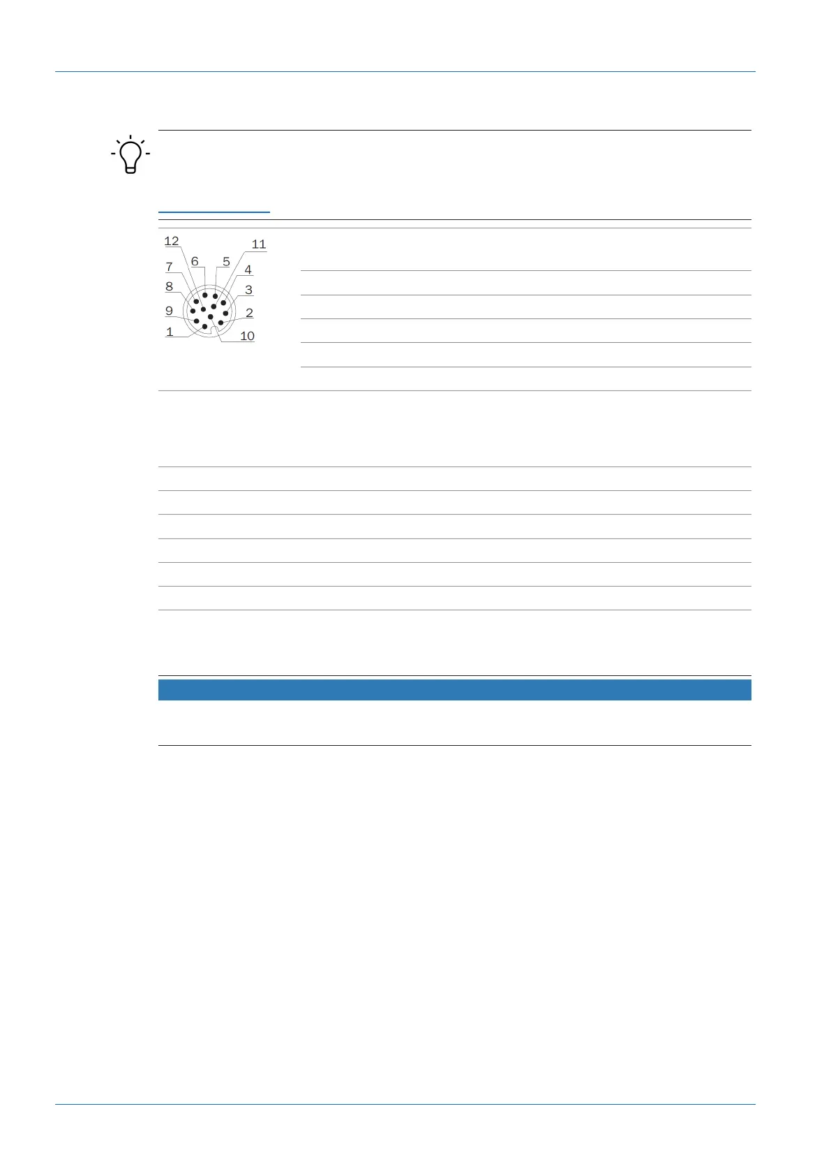
6.2 Pin assignment
INFO
The pin assignment described below is a maximum configuration. For the precise pin assign-
ment of your sensor, please see the data sheet that is available for download at
www.baumer.com.
1 Power (18...30VDC) /
IO-Link P24 (2L+)
2 GND /
IO-Link N24 (2M)
3 n. c. 4 Analog Out
5 n. c. 6 OUT 1 / IO-Link C/Q
7 RS485 / TX/RX+ 8 OUT 2
9 IN 1 (sync in) 10 RS485 / TX/RX-
11 Power / IO-Link L+ 12 GND /IO-Link L-
Pin 11 and pin 12 must be assigned even if not using IO-Link but OUT1.
Wire colors according to DIN IEC 757
1 BN – Brown 2 BU – Blue
3 WH – White 4 GN – Green
5 PK – Pink 6 YE – Yellow
7 BK – Black 8 GY – Grey
9 RD – Red 10 VT – Violet
11 GY-PK – Grey Pink 12 RD-BU – Red Blue
6.3 Connecting the sensor to electricity
NOTICE
Use a power unit for sensor supply. The USB interface is intended for data transfer only. Power
supply is always via the 12-pin M12 connector.
Instruction:
a) Ensure that the system is disconnected from power.
b) Connect the sensor according to the pin assignment.