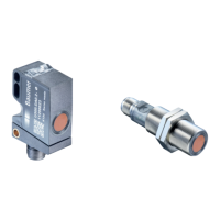
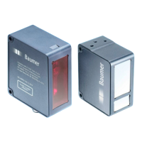
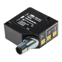
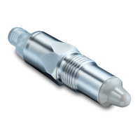
Ultrasonic sensors
U500 / UR18
Baumer Electric AG - CH-8501 Frauenfeld
Phone +41 (0)52 728 1122 - Fax +41 (0)63 739 1144
www.baumer.com
qTarget
®
qTeach
®
EN
DE
FR
IT
ES
CN
29.10.2018 / Version 1.1
Available Commands:
Teach-in commands, sensor element on/off, Find Me (Loca-
ting sensor) and more
Available Parameters:
Switching point, switching hysteresis, output function,
time fi lters, beam forming, measured value fi ltering, analog
output characteristic, function of Pin 5, LED status indicators
and more
Available Additional Data:
Switch counter, boot cycles, operation hours, device tempera-
ture, operating voltage, histograms
Models with IO-Link
SSC1/2/4: Switching Signal Channels
MDC: Distance Value or Switch Counter (selectable)
Quality: The quality bit signals a weak echo signal
Alarm: The alarm bit signals a problem with the
confi guration or the functionality of the sensor
Scale: Factor by power of ten, applicable to the value of
the Measurement Data Channel (MDC)
IO-Link Process Data Input
32 8 0
IntegerT(32) IntegerT(8) 8 bit
Measurement
Data Channel
(MDC)
Scale
Baumer specifi c
7 6 5 4 3 2 1 0
SSC4 Alarm Quality SSC2 SSC1
Related Models
U500 Models:
U500.D (Analog output)
U500.P (1-Point switch output)
U500.P (2-Point switch output)
U500.D (Analog output retro fi t version)
U500.R (Retro refl ective version)
U500.T/E (Through beam sensor (E-Receiver)(T-Emitter))
UR18 Models:
UR18.D (Analog output)
UR18.P (1-Point switch output)
UR18.P (2-Point switch output)
UR18.D (Analog output retro fi t version)
UR18.R (Retro refl ective version)
UR18.T/E (Through beam sensor (E-Receiver)(T-Emitter))
More Information related to these
products can be found on our website
(CAD, Beamcharts, CoC, Drawings, IODDs …)
www.baumer.com
Mounting Instructions
1
2
y
x
1
2
x = 3 x Sd
y = 2 x Sd
Mindestabstand zwischen zwei Sensoren
Minimal distance between two sensors
Distance minimale entre deux capteurs
Distanza minima tra due sensori
Distancia mínima entre dos sensores
传感器之间最小安装距离
Connection Diagrams
- Disconnect power before connecting the sensor.
- Voltage supply according UL 1310, Class 2
or device shall be protected by an external R/C or listed fuse, rated max.
30 VAC/3A or 24 VDC/4A
4
2 1
3
5
1-Point switch
2-Point switch
Refl ex Barrier
Analog measurement out
Through Beam Sensor
Analog measurement out
.P .P .R .D .E or .T .D (retro)
1 - Brown BN +Vs
2 - White WH n.c.
Push-Pull
out 2
n.c. U or I n.c. Teach-in
3 - Blue BU 0 V
4 - Black BK IO-Link / Push-Pull out 1 U or I
5 - Grey GY Teach-in / Sync / Mux selectable via IO-Link n.c.
Alignment Aid
Retro-refl ective and through beam version (.R and .E/.T) are
equipped with alignment aid, which is integrated in Teach
Level 1.
The Alignment aid indicates the strenght of the received
signal.
Retro-relfektive Sensoren und Einwegschranken (.R und
.E./.T) verfügen über eine Ausrichthilfe.
Diese ist im Teach Level 1 integriert und zeigt die Stärke des
empfangenen Signals an.
Les versions barrières réfl ex et barrières simples (R et E/R)
sont équipées d’un outil d’aide à l’alignement, qui est intégré
au niveau 1 de la procédure de teach.
L’aide à l’alignement indique la force du signal reçu.
Le version a retrorifl essione e sbarramento (.R e .E/.T) sono
dotate di indicazione di corretto allineamento integrata nel
Teach-in al livello 1.
Questa funzione indica l’intensità del segnale ricevuto.
镜反射和对射版本(.R和.E / .T)的传感器配备了对准辅助功
能, 集成在设定级别1中.
对准辅助表明了接收信号的强度.
Las versiónes retrorrefl ectiva y de barrera (.R y .E/.T) están
equipadas con una ayuda de alineado integrada en el Nivel
1 de Teach.
La ayuda de alineado indica la potencia de señal recibida.
Sensor ausrichten, schnelles Blinken, besserer Empfang
Align sensor, faster fl ashing, better reception
Aligner le capteur, clignotement plus rapide, meilleure est la
réception
Allineamento del sensore: Più è veloce il lampeggiamento
tanto più è forte il segnale
Sensor alineado, parpadeo más rápido, mejor recepción
对准传感器,闪烁越快,接收得更好
n
2
Faster fl ashing
→ stronger signal
Teach-in OK
Teach-in NOK
2 sec / Level 1
4 sec / Level 2
6 sec / Level 3
8 sec / Level 4
8
8
8 8
X
1 11
2 22
2 2
2 2
Enter Teach Level
- Place Tool as shown right or connect teach-
in wire to Vs+.
- Blue LED is getting brighter if tool/teach-in
is recognized properly.
- Remove after n sec for desired level.
A TAP is a short touch of the tool as shown
to the right.
General Information
- qTeach locks 5 min after power up, the blue LED turns off.
- In teach mode the output changes to 0 V.
- During operation the teach wire should be connected to 0V.
- For external teach-in, connect teach wire to +Vs.
- External teach-in is always possible (no locking).
- Place tool > 12 sec. : Leave Teach-in without changes.
1-Point Teach
Alignment Aid
(Uxxx.R, Uxxx.E)
Place Object & TAP
Scanning Range /
Window Teach
(Uxxx.P / Uxxx.D)
Place Object at
Position A & TAP
Place Object at
Position B & TAP
1-Point Teach out 2
(Uxxx.P with 2 outputs)
Place Object & TAP
Refl ector Tolerance
(Uxxx.R)
TAP to change
setting
Output Logic
TAP to change
setting
Optional: Hold 2
sec to change to
output 2
TAP to change
setting
Factory Reset
Do nothing for factory reset
Teach-in Instruction
Indication Tolerance
5 %
10 %
Indication Logic
NO, out 1
NC, out 1
Indication Logic
NO, out 2
NC, out 2
1
2
8
1
8
8
A
B
SP1
Hyst
Sensing direction
SP1
Hyst
Sensing direction
SP1
Hyst
Sensing direction
10 V /
20 mA
10 V /
20 mA
0 V /
4 mA
0 V /
4 mA
A < B
A > B
SP1
Hyst
Sensing direction
LED Indicators Green Yellow Red Blue
Power on
Short circuit
Output 1 active
Output 1 signal close
to threshold
Output 2 active
Output 2 signal close
to threshold
qTeach not locked
Teach-in mode see Teach-in Instruction
LED Indication Legend Operating Mode
LED on
LED fl ashing 1 Hz
LED fl ashing 2 Hz
LED fl ashing 8 Hz
U500.P / UR18.P with 1 output U500.D / UR18.D U500.P / UR18.P with 2 outputs U500.R / UR18.R
Level 1
1-Point Teach Output 1 1-Point Teach Output 1 1-Point Teach Output 1 1-Point Teach Output 1
Set the switchpoint SP of output 1 at
the position of the object
Set the switchpoint SP of output 1 at
the position of the object
Set the switchpoint SP of output 1 at
the position of the object
Teach-In the position of the
Refl ector (Distance)
Level 2
Window Teach Scanning Range / Window Teach 1-point Teach Output 2 Refl ector Tolerance
set a window in which an object
should be detected
Set the scanning range related
to the analogue value. Output 1
is active if an object is within the
scanning range
Set the switchpoint of output 2 at the
position of the object
Set the tolerance of the refl ector
position
The refl ector tolerance states the
relative allowable variance of the
refl ector position.
Example: Refl ector Position of
500 mm ± 5 % means the refl ector
position ranges from 475 mm to
525 mm.
Teach-In Description Level 1 & 2
Only sensors with 2 outputs do have a red LED
EN
1
2
8
1
8
8
SP1
Hyst
Sensing direction
SP1
Hyst
Sensing direction
SP1
Hyst
Sensing direction
10 V /
20 mA
10 V /
20 mA
0 V /
4 mA
0 V /
4 mA
A < B
A > B
SP1
Hyst
Sensing direction
LED Indikatoren Grün Gelb Rot Blau
Betriebsanzeige
Kurzschluss
Ausgang 1 aktiv
Ausgang 1 Signal
nahe der Schwelle
Ausgang 2 aktiv
Ausgang 2 Signal
nahe der Schwelle
qTeach verwendbar
Teach-in Modus
siehe Teach-in Anweisung
LED Anzeige Legende Betriebsmodus
LED leuchtet
LED blinkt 1 Hz
LED blinkt 2 Hz
LED blinkt 8 Hz
U500.P / UR18.P mit 1 Ausgang U500.D / UR18.D U500.P / UR18.P mit 2 Ausgängen U500.R / UR18.R
Level 1
1-Punkt Teach Ausgang 1 1-Punkt Teach Ausgang 1 1-Punkt Teach Ausgang 1 1-Punkt Teach Ausgang 1
Setzt den Schaltpunkt SP des Aus-
gang 1 an der Position des Objektes
Setzt den Schaltpunkt SP des Aus-
gang 1 an der Position des Objektes
Setzt den Schaltpunkt SP des Aus-
gang 1 an der Position des Objektes
Einlernen der Refl ektordistanz
Level 2
Fenster Teach Messbereich / Fenster Teach 1-Punkt Teach Ausgang 2 Refl ektortoleranz
Defi niert ein Schaltfenster, inner-
halb welches ein Objekt erkannt
werden soll
Defi niert den mit dem analogen
Ausgang verknüpften Messbereich.
Ausgang 1 ist aktiv, wenn sich ein
Objekt innerhalb des Messbereichs
befi ndet
Setzt den Schaltpunkt SP des Aus-
gang 2 an der Position des Objektes
Einstellung der Refl ektortoleranz
Die Refl ektortoleranz beschreibt
die relative, zulässige Varianz der
Refl ektorposition
Beispiel: Bei einer Refl ektorposition
von 500 mm und einer Toleranz von
± 5% wird der Refl ektor von 475 bis
525 mm erkannt.
Teach-In Beschreibung Level 1 & 2
Nur Sensoren mit 2 Ausgängen verfügen über eine rote LED
DE
Teach-in OK
Teach-in NOK
2 sec / Level 1
4 sec / Level 2
6 sec / Level 3
8 sec / Level 4
8
8
8 8
X
1 11
2 22
Allgemeine Information
- qTeach verriegelt 5 min nach dem Einschalten, die blaue LED erlischt.
- Im Teachmodus wechselt der Ausgang auf 0 V.
- Im Normalbetrieb muss die Teachleitung auf 0 V gelegt werden.
- Für externes Teach-in, Teachleitung entsprechend mit Vs+ verbinden.
- Externes Teach-in ist immer möglich (keine Verriegelung)
- Werkzeug platzieren > 12 Sek. : Verlasse Teach-in ohne Änderungen.
1-Punkt Teach
Ausrichthilfe
(Uxxx.R, Uxxx.E)
Objekt platzieren
& TAP
2-Punkt Teach /
Fenster
(Uxxx.P / Uxxx.D)
Objekt platzieren an
Position A & TAP
Objekt platzieren an
Position B & TAP
1-Punkt Teach
out 2
(Uxxx.P mit 2 Ausgängen)
Objekt platzieren
& TAP
Refl ektortoleranz
(Uxxx.R)
TAP um Einstellung
zu ändern
Ausgangslogik
TAP um Einstel-
lung zu ändern
Optional: 2 sec
halten -> zu Aus-
gang 2
wechseln
TAP um Einstel-
lung zu ändern
Werkseinstellungen
Keine weiteren Eingriffe nötig
Teach Level auswählen
Ein TAP ist eine kurze Berührung mit dem
Werkzeug, wie rechts gezeigt.
Teach-in Anleitung
Anzeige Toleranz
5 %
10 %
Indikation Logik
NO, out 1
NC, out 1
Indikation Logik
NO, out 2
NC, out 2
Only regarding to retro version:
- Level 1 has the same functionalities as Level 2
- Level 3 has the same functionalities as Level 4
Gilt nur für Retro-Version:
- Level 1 hat die gleichen Funktionalitäten wie Level 2
- Level 3 hat die gleichen Funktionalitäten wie Level 4
2
2
2
2
- Platzieren Sie das Werkzeug wie rechts gezeigt
oder verbinden Sie die Teachleitung mit +Vs.
- Die blaue LED leuchtet hell, wenn das Tool /
Teach-In korrekt erkannt wird.
- Nach n Sek. entfernen, um das gewünschte
Level auszuwählen.