
A
Ashley ThompsonAug 4, 2025
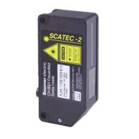
What to do if Baumer Accessories Scatec counts less copies than actually pass the sensor?
- AAnthony YoungAug 4, 2025
If your Baumer Accessories Scatec counts fewer copies than are actually passing the sensor, there are several potential causes and solutions: * **Wrong sensitivity setting:** Set DIP-switch 4 off. * **Incorrect copy distance:** Adjust the distance of the copies to ensure they are within the sensor's effective range. * **Overlap spacing issues:** Increase the overlap spacing or reduce the conveying speed. * **Coverage Problem:** Prevent copies from completely covering each other. * **Conveying speed too high:** Reduce the conveying speed. * **False pulse suppression:** Deactivate false pulse suppression (DIP-switch 3 set off) or make overlap more regular or accelerate slower.