EasyManuals Logo

Baumer SCATEC-2 FLDK 110 Series User Manual

Baumer SCATEC-2 FLDK 110 Series
18 pages
To Next Page IconTo Next Page
To Previous Page IconTo Previous Page
Page #12 background imageLoading...
Page #12 background image
Manual SCATEC-2 23 Baumer Electric AG
Version 2011-05
www.baumer.com
Frauenfeld, Switzerland
10.2 Electrical data
Operating voltage V
S
Limits: +10 VDC to +30VDC (UL-Class 2)
reverse-protected yes
Ripple V
S
10% within the limits of V
S
Power consumption < 2 W
Current consumption
Average: < 170 mA
Peak (after switching on) < 180 mA
Output connector
FLDK.../S14 M12 connector, 5-pole
FLDK.../S42 DIN 45322, 6-pole
FLDK110x10/xxxxxx see section 14
Output circuit
FLDK 110G... Push-pull
normal state low
FLDK 110C... Opto-isolated
switchable voltage maximum 40 V
load resistance maximum 50 kOhm
current load: max. 100 mA
short-circuit protected yes
Output pulse length
FLDK...1003/…and ...1005/… 5, 10, 15, 20 ms selected by DIP switch
FLDK...1006/… 5, 10 ms selected by DIP switch
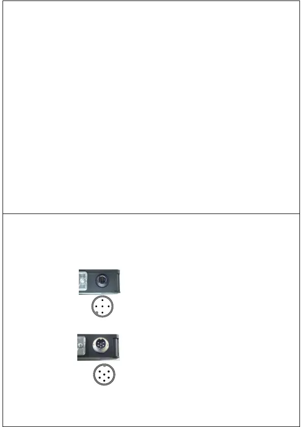
Manual SCATEC-2 24 Baumer Electric AG
Version 2011-05
www.baumer.com
Frauenfeld, Switzerland
10.3 Pin assignment
FLDK.../S14 M12-connector, 5-pole
FLDK.../S42 DIN 45322, 6-pole
Pin Assignment
1 Operating voltage +Vs
2 Seriell TxD (sensor)
3 GND (0V)
4 Signal output +Vout
5 Seriell RxD (sensor)
Pin Assignment
1 Signal output +Vout
2 not connected (FLDK 110G...)
Signal output -Vout (FLDK 110C...)
3 Operating voltage +Vs
4 Seriell RxD (sensor)
5 Seriell TxD (sensor)
6 GND (0V)
31
2
5
4
3
4
2
1
5
6

Questions and Answers:

Question and Answer IconNeed help?

Do you have a question about the Baumer SCATEC-2 FLDK 110 Series and is the answer not in the manual?

Baumer SCATEC-2 FLDK 110 Series Specifications

General IconGeneral
BrandBaumer
ModelSCATEC-2 FLDK 110 Series
CategoryAccessories
LanguageEnglish

Related product manuals