DIP-switch settings:
The effects of the various DIP-switch settings are
described in Section 9 Instructions for use below
FLDK 110x1003/Sxx
FLDK 110x1005/Sxx FLDK 110x1006/Sxx
Factory settings
Parameter
DIP-
switch
Setting Value
off / off 5 ms
off / on 10 ms
on / off 15 ms
Output pulse
length
1 / 2
on / on 20 ms
off inactive False pulse
suppression
3
on Active
on reduced
Sensitivity 4
off maximum
Parameter
DIP-
switch
Setting Value
off leading Running
direction
1
on trailing
off 5 ms Output pulse
length
2
on 10 ms
off inactive False pulse
suppression
3
on active
on reduced
Sensitivity 4
off maximum
Factory setting
o Do remount the cover after having set the
DIP-switch to avoid intrusion of dust
9 Instructions for use
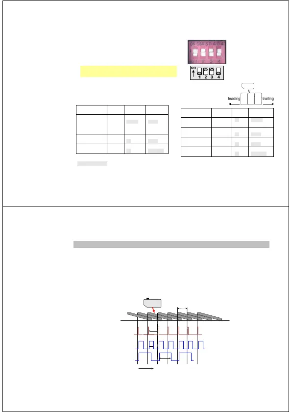
9.1 Output pulse length and maximum counting rate
On the one hand, the duration of an output pulse must be long enough so that the customer’s control
system can process it. On the other hand, the length of the output pulse limits the maximum counting
rate. Because output pulses must not overlap, the interval between edges must be at least as long as
one output pulse length. If the interval is shorter, then this edge will be suppressed meaning that the
edge will not initiate an output pulse.
The following figure illustrates how every other edge is suppressed because of a too long of an output
pulse length.
amber edge-LED
output pulse
pulse length p < interval a
on
off
high
low
time
p
high
low
output pulse
pulse length p > interval a
some edges are suppressed!
a
p
a
Scatec-2
 Loading...