9
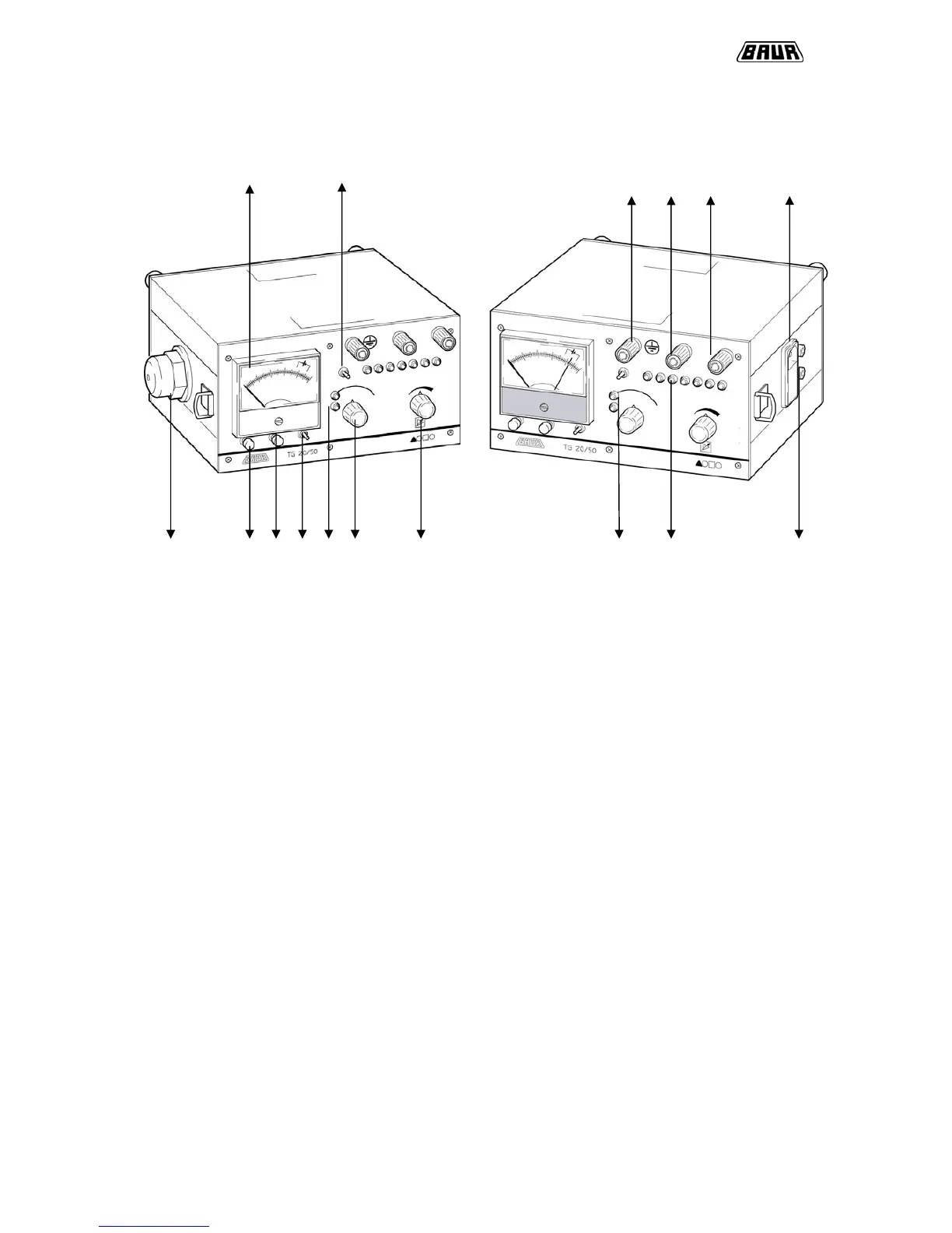
2.1.1 TG 20/50
3 9 14 13 13 11
15 7 8 6 2 5 10 1 4 12
Display elements:
1 Power control
2 Charge control
3 Pointer instrument for I
out
and I
in
and battery control
4 Indication of impedance level
Operating elements:
5 ON switch and mode selector
6 Button for battery control and instrument illumination
7 Button for indication of I
in
8 Button for switching measuring range x 0.1 for I
out
9 Button for automatic or manual impedance adjustment
10 Regulating switch for output current
Interfaces:
11 Mains connection
12 Connection for external battery
13 Output socket
14 Protective earth terminal
15 Connection for loop antenna