Page 6
IP Series Codec Installation and Operating Instructions
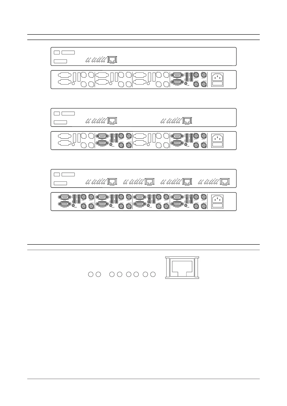
IP-CODEC GENERAL LAYOUT
Single-way IP CODEC Front and Rear Panels (IP-ENC1-R and IP-DEC1-R)
Two-way IP CODEC Front and Rear Panels (IP-ENC2-R, IP-DEC2-R and IP-ENC1DEC1-R)
Four-way IP CODEC Front and Rear Panels (IP-ENC4-R, IP-DEC4-R and IP-ENC2DEC2-R)
Note: On combined Encoder/Decoder units, the decoder modules are always on the right hand side of the unit when
viewed from the front. Powering-up the unit will allow this to be determined by observing the state of the ENC/DEC led.
FRONT PANEL INDICATORS
NETW
RK
POWER
ACTIVE
ENC/DEC
AUDIO
SERIAL IN
SERIAL OU
NTSC/PAL
VID ST
A
T
Each channel of the IP-Codec has a common set of led indicators whose function is described below.
POWER This led indicates that power is supplied to the unit.
ACTIVE This led flashes to indicate that the unit is functioning correctly
ENC/DEC This led indicates the functional mode of the IP-Codec. If the led is off, the unit is in the DECODER mode.
If the led is ON, the unit is in the ENCODER mode.
AUDIO This led indicates that audio streaming is taking place from, or to the unit.
SERIAL IN This led indicates that serial data streaming to the unit is taking place.
SERIAL OUT This led indicates that serial data streaming from the unit is taking place.
NTSC/PAL This led indicates the video mode of the unit. If the led is OFF, the unit is in NTSC video mode. If the led is
ON, the unit is in PAL video mode. If the led flashes, this indicates video-loss or no video to the unit.
VID STAT This led indicates the video streaming status of the unit. If the led is off, there is no video input to the
device. If the led is on, video streaming is taking place.