33
I N S TA L L E R S e c t i o n ( e n )
7733595 (01-05/19)
11.2 ACCESSORIES NOT INCLUDED IN THE SUPPLY
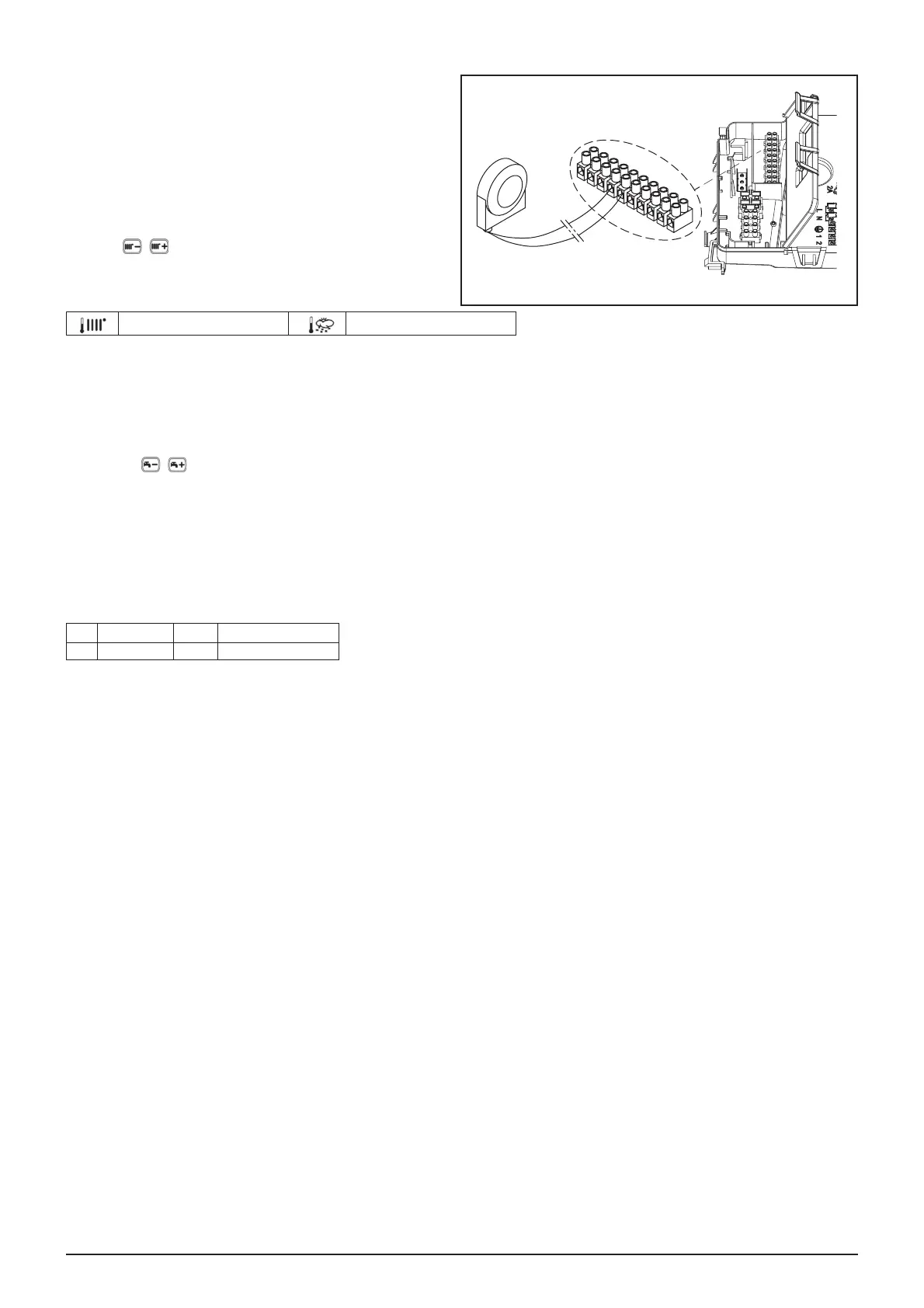
11.2.1 EXTERNAL SENSOR
7RFRQQHFWWKLVDFFHVVRU\VHH¿JXUHWRVLGHWHUPLQDOV4-5)
DQGWKHLQVWUXFWLRQVVXSSOLHGZLWKWKHVHQVRU
SETTING THE "Kt" CLIMATE CURVE
When the external sensor is connected to the boiler, the
HOHFWURQLF ERDUG DGMXVWV WKH ÀRZ WHPSHUDWXUH FDOFXODWHG
according to the set KtFRHႈFLHQW6HOHFWWKHUHTXLUHGFXUYHE\
pressing
as indicated in the chart in annex SECTION
E for selecting the most appropriate one (00 to 90).
KEY TO CHART - “SECTION” E
)ORZWHPS Outside temp
11.2.2 EXTERNAL STORAGE BOILER
The boiler can be electrically connected to an external storage boiler. A diagram of the hydraulic connection of the external
VWRUDJHERLOHULVVKRZQLQDQQH["SECTION" F. Connect the DHW priority sensor NTC to terminals 9-10 on terminal block M2.
7KHVHQVLWLYHHOHPHQWRIWKH17&VHQVRUPXVWEHLQVHUWHGLQWKHVSHFLDOZHOOORFDWHGRQWKHVWRUDJHERLOHU0DNHVXUHWKDWWKH
H[FKDQJHFDSDFLW\RIWKHVWRUDJHERLOHUFRLOLVDSSURSULDWHIRUWKHSRZHURIWKHERLOHU$GMXVW'+:WHPSHUDWXUH&&
by pressing
.
IMPORTANT: set parameter P03 = 05 as described in section 14.
11.2.3 CONNECTING TO A ZONE SYSTEM
To use this function, install the programmable relay electronic board supplied as an accessory.
KEY TO ELECTRICAL CONNECTIONS (see diagram in annex "SECTION" G at the end of this manual).
Z Zone (1..n) EV Zone electrovalve
R Relay RT Room thermostat
7KHERLOHUFDQPDQDJHD]RQHKHDWLQJV\VWHP7KH5RRP8QLWZDOOPRXQWHGFDQEHXVHGWRFRQWURORQH]RQHZKLOHQRUPDO
ambient thermostats can be used to control the other zones.
SYSTEM CONNECTIONS
• &RQQHFWWKH]RQHYDOYHSXPSWRWHUPLQDOVRIWKHUHOD\ERDUGWHUPLQDOEORFNLQVLGHWKHERLOHUFRQWUROER[
• Connect the Ambient Thermostat contact of the other zones to terminals 1-2 of terminal block M1 (CONNECTING THE
AMBIENT THERMOSTAT section).
Check that parameter P04=02. Set parameter P10 (SETTING PARAMETERS section).
SIEMENS
QAC34
1
9
8
7
6
5
4
3
2
10
M2
CG_2394