8
4 ACCESSING THE PARAMETER CONFIGURATION MENUS
Display key
The list of configuration menus is as follows:
• Info (chapter 2.1)
• Time and date (chapter 2.2)
• User interface (chapter 2.3)
• Hour programming(1, 2 - chapter 6)
• Hour programming 3 / CC3 (chapter 6)
• Hour programming 4 / DHW (chapter 6.3)
• Hour programming 5
• CC circuit holidays (1,2,3 - chapter 4.2)
• Heating circuit (1,2,3 - chapter 4.1.1)
• Domestic hot water
• Instant DHW water heater (not used on this type of boiler)
• Error (chapter 9)
• Generator diagnostic
The procedure below must be followed
to acces the list of configuration menus (refer to the «Symbol
description» chapter:
C then B to choose the menu you want;
B to confirm or C to exit without saving.
4.1 Information menu
If an anomaly occurs, the first item of data displayed is its code.
To display the boiler’s information, select the «Info» menu key C -> B -> B to confirm.
4.2 Setting the date and time
To set the date and time, proceed as follows:
• C B select the menu Time and date B 1 (Hours / minutes) B (the hour flashes)
• B to modify the hour B to confirm (the minutes flash) B to modify B to confirm.
• B to modify 2 (Day / month) and 3 (Year) by carrying out the procedure above again.
• C to return to the previous menu.
4.3 Modifying the language (user interface menu)
To select the language,
proceed as follows:
• C B select the menu to select the program line 20 (Langue)
• B to choose the language B to save.
• C to return to the previous menu.
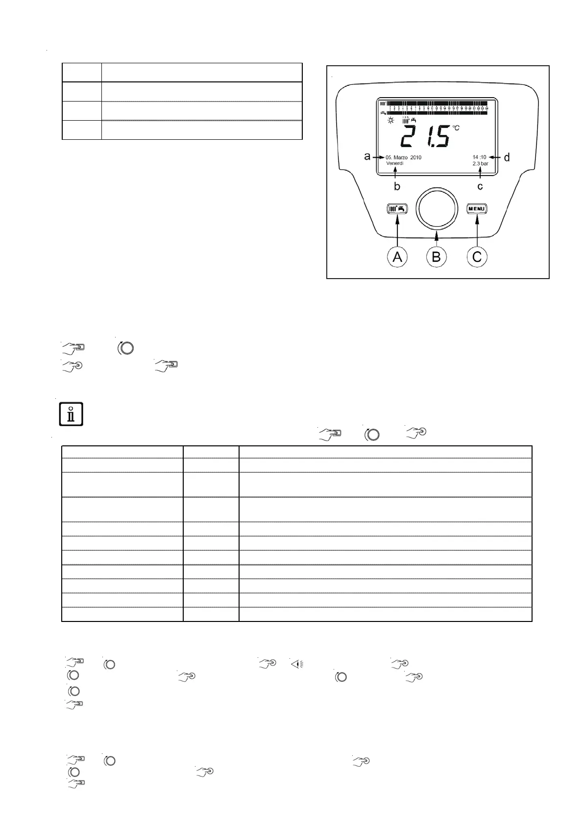
a
Date: day, month, year
b
Day of the week
c
Boiler pressure / Heating circuit
d
Clock: hour and minute
Boiler temperature °C Boiler flow -back temperature
Outdoor temperature °C Outdoor temperature
Min. outdoor temperature °C
Minimum outdoor temperature value stored
(w ith Outdoor Probe connected)
Max. outdoor temperature °C
Maximum outdoor temperature value stored
(w ith Outdoor Probe connected)
DHW te m pe ratur e °C DHW temp (value read by the boiler's domestic circuit sensor)
Collector temperature °C Instant collector probe temp. (w ith solar installation coupling)
Heating circuit state (1,2,3) On/Off" Heating circuit operating mode (circuits: 1,2,3)
DHW circuit state Load Domestic circuit operating mode
Boiler state On/Off" Boiler operating mode
Solar installation state - Indicates the solar operation (w ith solar installation integration)
Customer service telephone No. xxxxxxxxxx