Do you have a question about the Baxi Solo 3 and is the answer not in the manual?
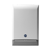
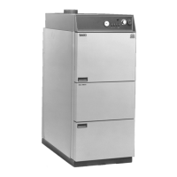
Details the Baxi Solo 3 PFL System boiler and its features, including model outputs.
Outlines general installation requirements and adherence to regulations for the appliance.
Provides crucial advice on handling man-made mineral fibre components within the appliance.
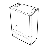
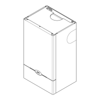
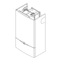
Identifies and labels the main components of the boiler through diagrams and a list.
Specifies requirements for fully pumped sealed systems and general system conditions.
Details the necessity and procedure for flushing and treating water systems to prevent corrosion.
Explains the boiler's pump overrun device and requirements for system bypass circuits.
Covers pipe sizes and connection types for the boiler's flow and return pipes.
Lists requirements for system components regarding operating temperature and pressure.
Recommends control systems for optimum operation, including timers and thermostats.
Specifies requirements for using approved thermal or heat stores with the boiler.
Guides on the procedure for filling and pressurising the central heating system.
Details the appliance's expansion vessel capacity and requirements for larger systems.
Explains the operation, discharge pipe requirements, and safety settings of the relief valve.
Provides guidelines for selecting a suitable installation location for the appliance.
Specifies necessary clearances around the appliance for installation and servicing.
Outlines general requirements for siting balanced flue terminals, including protection measures.
Details available flue extensions and maximum lengths for various flue configurations.
Addresses ventilation requirements when the appliance is installed in a cupboard or compartment.
Covers requirements for gas installation and appliance connection.
Details electrical connection requirements, including earthing and isolation.
Describes the initial steps for preparing the appliance for installation, including component removal.
Continues the preparation steps, focusing on wall plate positioning and flue hole marking.
Explains how to fit the fan outlet restrictor for rear flue installations.
Details how to prepare components for a rear flue installation based on wall thickness.
Guides on assembling the rear flue duct, air duct, and terminal assembly.
Covers fitting the wall plate, making good around the air duct, and attaching the flue trim.
Provides instructions for fitting the appliance with left or right hand side flues.
Details preparing components for side flue installations, including calculating and cutting flue lengths.
Describes two methods (A & B) for fitting the flue and wall plate assembly.
Continues the instructions for Method A of fitting the flue and wall plate assembly.
Provides instructions for Method B of fitting the flue and wall plate assembly.
Advises on obtaining and ordering terminal guards for the appliance.
Details the procedure for positioning and fixing a terminal guard to the wall.
Explains how to install the internal fitting kit for walls of specific thicknesses.
Continues the instructions for installing the internal fitting kit, including sealing and securing.
Covers connecting the pipes and performing the initial system flush.
Details the process of fitting the combustion box assembly to the wall plate.
Provides a wiring diagram and key for all electrical connections to the appliance.
Guides on routing and connecting the supply cable to the boiler's terminals.
Outlines the step-by-step process for commissioning the boiler after installation.
Continues the commissioning procedure, including burner pressure checks and system balancing.
Describes how to fit the outer case, including infill panels and securing the door.
Explains the function of the manual reset overheat cut-off device and how to reset it.
Details the steps required to safely dismantle the boiler for annual servicing.
Provides instructions for cleaning the combustion box components, including burner and baffles.
Explains how to clean the heat exchanger fins to ensure efficient operation.
Guides on removing, cleaning, and refitting the burner injector.
Details the procedure for cleaning the pilot assembly, including electrode and injector.
General safety precautions before changing any boiler components.
Step-by-step guide for replacing the main circuit board of the appliance.
Instructions for disconnecting and replacing the ignition electrode.
Details the procedure for replacing the gas valve, including electrical and pipe connections.
Instructions for disconnecting and replacing the thermostat sensor.
Guides on how to disconnect and replace the overheat thermostat.
Instructions for removing and fitting a new fan assembly for the appliance.
Details how to disconnect and replace the pressure switch.
Instructions for removing and refitting the burner assembly.
Guides on replacing the burner injector.
Details how to replace the pilot burner injector.
Instructions for removing and refitting the gas manifold.
Steps for replacing only the pump head of the appliance.
Instructions for replacing the complete pump assembly.
Guides on how to replace the pressure gauge on the appliance.
Instructions for replacing the pressure relief valve.
Details the procedure for repressurising the expansion vessel after maintenance.
A list of common replacement parts with their key numbers and manufacturer part numbers.
Detailed instructions for testing the potentiometer using a multimeter.
Specific instructions for testing potentiometers with a two-pin connector.
| Category | Boiler |
|---|---|
| Flue Type | Conventional Flue |
| Warranty | 2 years |
| Model | Solo 3 |
| Fuel Type | Natural Gas |
| Mounting | Wall Mounted |