4
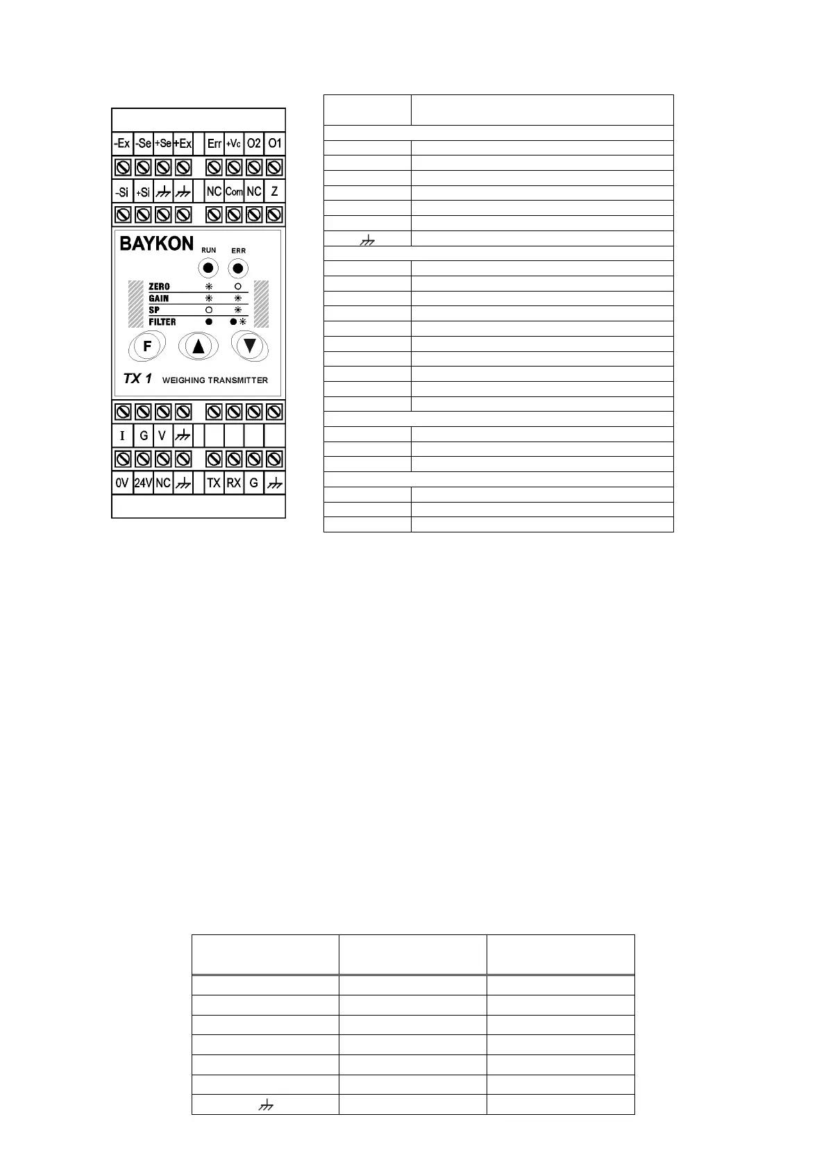
Pin Name Definition
LOAD CELL CONNECTION
- Ex - Excitation
- Se - Sense
+ Se + Sense
+ Ex + Excitation
- Si - Signal
+ Si + Signal
Shield
DIGITAL I/O (only TX 1W)
Err Error output
+ Vc Common +24V DC for digital outputs
O1 Digital output no. 1
O2 Digital output no. 2
NC Not Connected
Com Zeroing input (0 V)
Z Zeroing input (+24 V)
TX TXD ( RS232C )
RX RXD ( RS232C )
G Ground ( RS232C )
ANALOGUE OUTPUT
I 4 - 20mA output
G GND
V 0 - 10V output
POWER SUPPLY
0V 0 V
24V 24 VDC
NC Not Connected
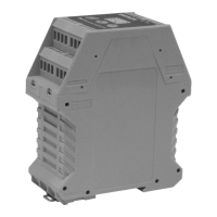
Figure 2. TX 1 24 VDC front view and pin layout
Do not forget to connect the shield of the load cell cable and the analogue output
cable to TX 1 at the correct ground terminals.
The quality of the grounding of your system provides the accuracy of your weighing system beside
its safety. If the condition of the power line in the plant is bad, prepare a special power line and
grounding.
If you have to service the instrument, turn off the power and wait at least for 30 seconds before
interfering.
Perform the other connections to TX 1 as described below.
2.3. Load Cell Connection
The load cell wiring should be made carefully before energizing to avoid damages to the
instrument and the load cells. The input resistance of the load cells that you want to
connect should be more than 85 Ω. The sense pins of the instrument must absolutely be
connected. In 4-wire installations the sense and the excitation pins with the same polarity
should be short circuited at the connector side.
Pinout Name 6 Wire Load Cell
Connection
4 Wire Load Cell
Connection
+Ex + Excitation + Excitation
+Se + Sense + Excitation
-Se - Sense - Excitation
-Ex - Excitation - Excitation
+Si + Signal + Signal
-Si - Signal - Signal
Shield Shield
 Loading...