5
2.4. Analogue Output Connection
There are 2 analogue outputs on TX 1; one is for 0 – 10 volt and the other for 4 – 20 mA.
But only one of them can be used at the same time and has to be selected in the setup
mode.
The wiring of the analogue output should be done according to the pin configuration given
in the table below.
Pin Name Definition
V 0 - 10 V Output
I
4 - 20mA Output
G GND
Shield
2.5. Input and Outputs (only TX 1W)
TX 1W has one zeroing input, one error output and two setpoint outputs. If an input signal
is supplied to the zeroing input, the analogue output signal of TX 1W will be set to “0 kg”.
The setpoints will be active when the weight value is higher than the entered setpoint
value.
If any failure occurs within TX 1W, an error output will be passive and the LED on the front
panel will be lightened.
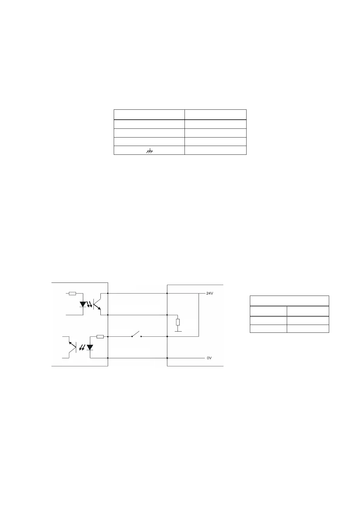
If you want to use these I/O’s, prepare the circuits as shown below.
Figure 3. Digital I / O connection diagram and error output description
2.6. Serial port RS232C (only TX 1W)
Serial port can be used for eCal electronic calibration, adjusting filter value, entering
setpoint values and following status etc.
The pin configuration of this port can be seen in Figure 1 and 2.
Error Output
Status Definition
1 In function
0 Error
Error or setpoint
Common
R
load
 Loading...