Page9
ATS11 Front, ATS22 similar Front
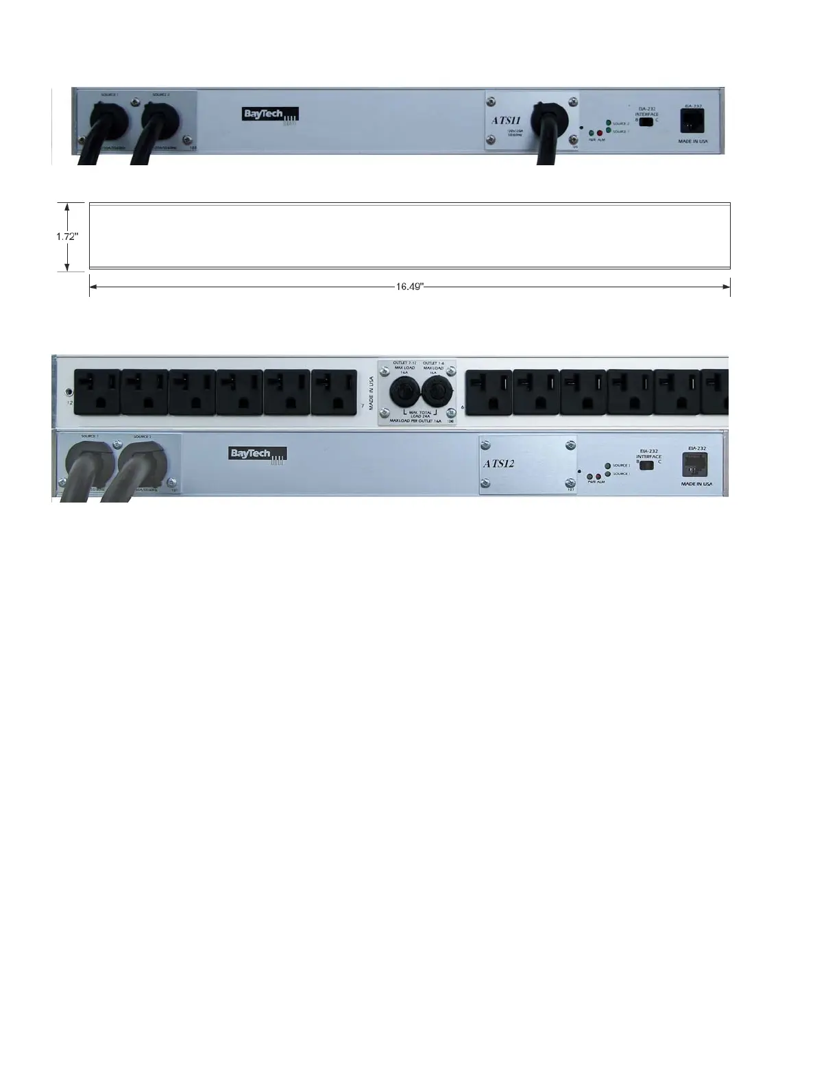
ATS11/ATS22 Rear
ATS12 Rear on Top, Front on Bottom
ATS23 similar Rear but UL489 Breakers on Front panel
ATS11 and 12 same dimensions
Rear Switch & Indicators:
EIA232 INTERFACE B/C = Set switch to ‘B’ for normal operations. ‘C’ changes the pin out to allow
for Cisco’s PC cable to operate in most cases but not all.
Indicators:
ALM = Red LED Over-current alarm or an abnormally input voltage
PWR = Green LED power is connected to the unit through either source 1 or 2
Source 1 = Green LED lit indicates unit is using Source 1 as the Input power
Source 2 = Green LED lit indicates unit is using Source 2 as the Input power
Only one of the source LEDs will be lighted at a time, the source supplying power to the outlet(s).
Front Switch & Indicators:
None