Do you have a question about the BayTech DS3 and is the answer not in the manual?
Lists user-programmable features for DS71/DS71-MD2 host modules, including serial port settings and device identification.
Instructions for connecting the DS-Series to a computer using an EIA-232 serial connection and setting communication parameters.
Details on powering on the DS-Series module and accessing the main menu interface.
Explains how to select a device from the main menu or using ASCII character strings.
Guide to accessing the configuration menu for different DS modules (DS71, DS74, DS73).
Procedures for unpacking, checking contents, and preparing the installation site for the DS-Series unit.
Safety precautions and guidelines for powering the DS-Series unit, including grounding and module replacement.
Information on MJ-45 ports, crossed modular cables, and adapters for connecting EIA-232 devices.
Instructions for connecting the DS73TP module to a network hub using a 10Base-T cable.
Guidance on connecting external modems to the DS71-MD2 host module using RJ-11 and MJ-45 ports.
Illustrations and part numbers for crossed 8-pin modular cables and DE-9 PC serial port adapters.
Detailed steps for connecting the DS71 Host Module to EIA-232 devices using various adapters and cables.
Instructions for using the DS71-MD2's internal modem for remote access, including priority over serial ports.
Steps for connecting an external modem to the DS71 or DS71-MD2 via EIA-232 serial port and telco jack.
Guide to connecting the DS73TP module to a network hub via a 10Base-T Ethernet connection.
How to power on the DS-Series unit and access its main menu interface, showing example menus for DS71 and DS71-MD2.
Explains two methods for selecting a device: menu-driven and ASCII character string, with examples.
How to place a port in binary mode for reliable data transmission and how to terminate it.
Steps for establishing a PPP connection using Windows 95 Dial-Up Networking with the DS73TP module.
Guide to configuring DS71/DS71-MD2 modules via menu selection or ASCII string commands, detailing menu options.
How to view the status of user-programmable features by selecting the 'Status' option in the configuration menu.
Details on translating data for different serial configurations and default settings for DS-Series host modules.
How to assign a user-programmable name to identify ports on DS71/DS71-MD2 modules for easier management.
Defines the ASCII character string used to select an I/O port on a DS74 module, with default value '$BT'.
Describes the character used to invoke the main menu and how to change the default semicolon.
Feature to provide reliable binary data transmission by adding a timeguard after receiving the attention character.
Enables identification of module and port number upon connection, allowing echo of module/port or device name.
Configures how the host modem responds upon login, including header, menu, password, and auto-connect port settings.
Enables or disables the header displayed upon login, showing its default status and how to change it.
Guides on changing or enabling/disabling password protection for login and configuration access.
Explains how to enable/disable the main menu upon login, and its interaction with auto-connect features.
Details on configuring automatic connection to a specific port upon login or power-up, with usage notes for different models.
Explains the DCD Logon/Logoff feature which prevents unwanted modem connections by requiring login.
Configuration options for the DS71-MD2's internal modem, including rings to answer, Xon/Xoff, and timeouts.
How to set or change the unique identifier for the DS-Series module, which appears in the main menu.
Procedure to reset power to all I/O ports on peripheral modules using the 'RM' command.
Steps for resetting the DS-Series unit using menu or ASCII commands, noting that it terminates connections but not selections.
Details on programming serial port parameters (1-8) for the DS74 module, including saving changes.
Instructions for setting a port device name for the DS74 module, which works as previously described.
Procedure to configure the DS73TP's IP address, required before network access.
Configuration of the Dial-Up IP Address for the DS73TP, which must differ from the Module IP Address.
Setting the Subnet Mask for the DS73TP, crucial for network access and packet routing.
Configuring the Gateway address for the DS73TP, necessary for connecting to external networks.
Setting the Primary Domain Name System server address for the DS73TP for name resolution.
Setting the Secondary Domain Name System server address for the DS73TP for redundancy.
Configuring the Primary Net BIOS Name Server address for the DS73TP for network name resolution.
Configuring the Secondary Net BIOS Name Server address for the DS73TP for network name resolution.
Setting the user name required for network connections, noting that it is case-sensitive.
Setting the password required for network connections and configuration access, noting it is case-sensitive.
Assigning a unique name to the DS73TP module for identification purposes during connections.
A table to record DS-Series unit model, serial numbers, module details, adapters, cables, and software program.
Steps for returning the unit for service, upgrade, or repair, including obtaining a Return Authorization Number.
Summary of common AT commands for U.S. Robotic modems, including their interpretations.
Summary of common AT commands for Rockwell chip set modems, similar to U.S. Robotic commands.
Steps within Windows 95 to initiate a new dial-up connection, including naming and modem selection.
Configuring connection properties like server type, protocols, and TCP/IP settings for PPP connections.
Displays the menu that appears after a successful connection to the DS73TP module.
Diagrams showing the mechanical layout of DS71, DS71-MD2, DS74, and DS73 modules.
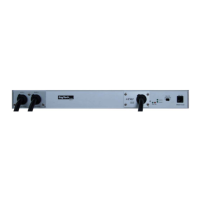
Diagrams showing the front panel layout of DS71, DS71-MD2, DS73TP, and DS74 modules.