Chapter Four
Block Diagram of Unit Circuit
4.1 Servo Circuit
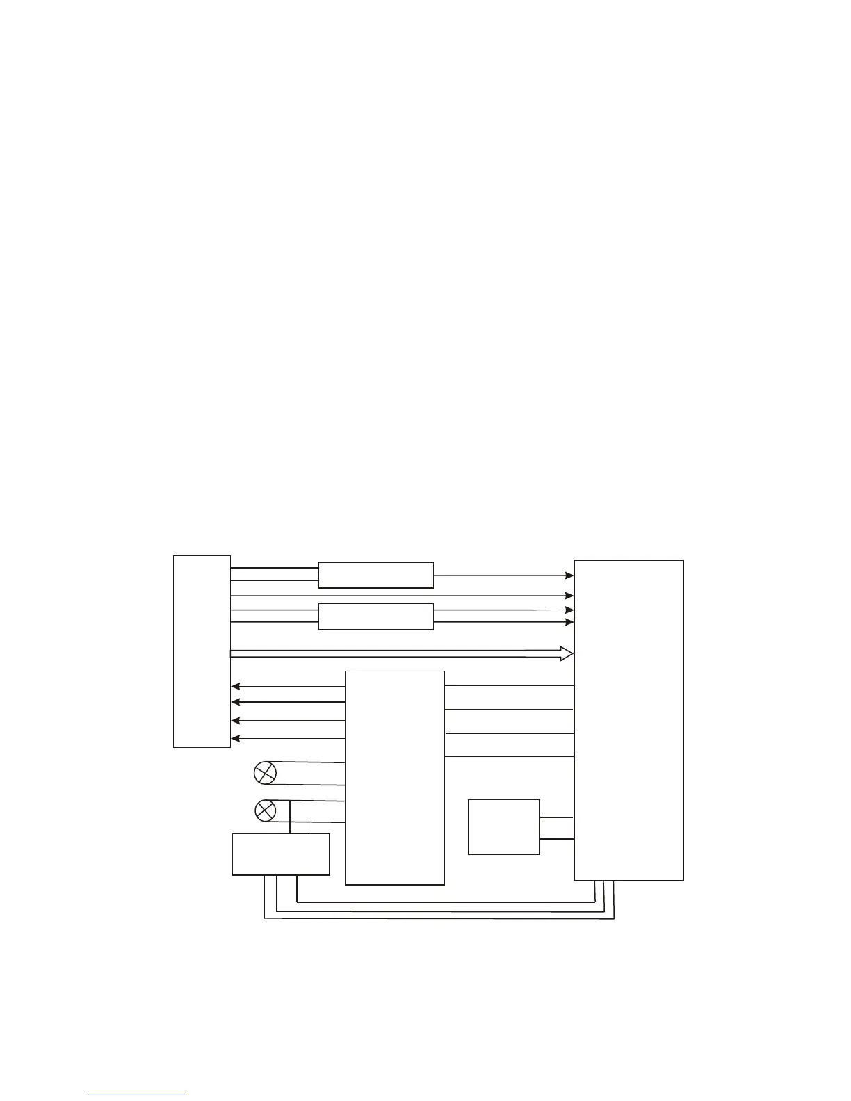
Servo system of this machine adopts SONY loader and MTK decode scheme. And servo circuit is
mainly composed of front signal processing, digital servo processing, digital signal processing chip
MT1389 and driving chip AM5888. MT1389 is also main part of decode circuit. Block diagram of servo
circuit is shown in figure 4.1.1.
FOSO
FMSO
TRSO
DMSO
A B C D E F RFO
IOA
LDO2
LDO2
MDI1
Disc switch circuit
Laser power
control circuit
Spindle control
detecting circuit
Spindle Motor
Feed Motor
XS1
AM5888
MT1389L
Door open/
close circuit
T-
T+
F+
F-
SL+
SL-
SP-
SP+
1
23
4
26
15
16
14
13
17
18
12
11
Figure 4.1.1 Block diagram of servo circuit
- 17 -