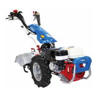
•
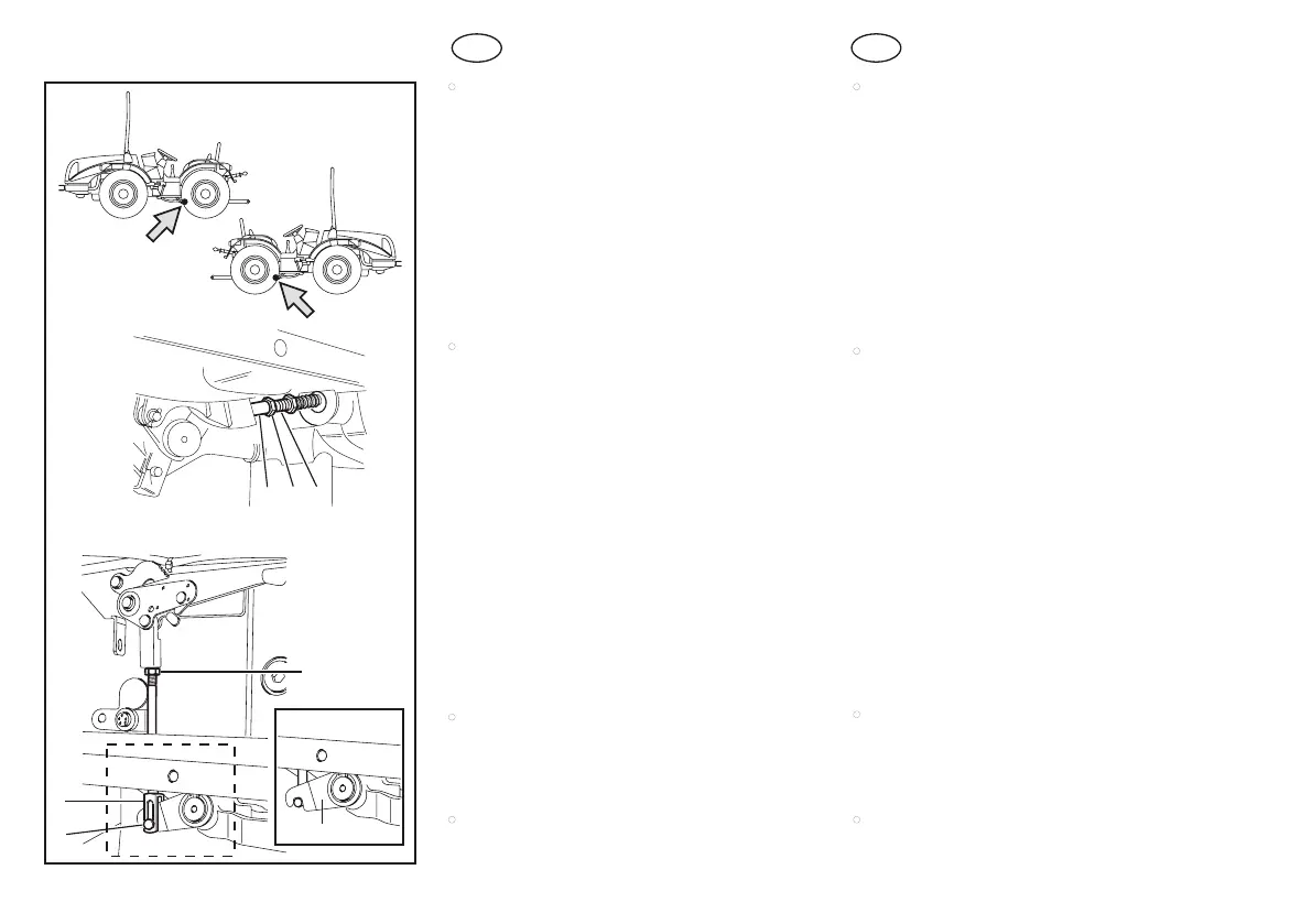
Controllare che i pedali di comando abbiano
una corsa a vuoto di circa 20 mm.
La regolazione descritta di seguito deve es-
sere eseguita su entrambi i tiranti di coman-
do (4, fig. 4) dei freni di servizio.
– Se la corsa a vuoto dei pedali (o pedale nella
ver.
) è eccessiva, registrare i tiranti (3, fig.
20), agendo sul dado (1). Al termine della rego-
lazione serrare il controdado (2).
•
Controllare che con la leva di comando tirata le
ruote siano bloccate.
– Se è necessaria la regolazione, sganciare il
perno (6, fig. 20) dalla forcella (5), allentare il
controdado (7) e ruotare come necessario la
forcella (5).
– A regolazione effettuata, serrare il controdado
(4), dopo aver riposizionato il perno con fermo
di sicurezza (6).
A differenza della versione RS nella versio-
ne
la regolazione deve essere effet-
tuata liberando prima il tirante con perno dal
gancio (7).
•
Attenersi alle indicazioni riportate nel relativo
manuale d’uso e manutenzione.
•
Attenersi alle indicazioni riportate nel relativo
manuale d’uso e manutenzione.
•
Check if the control pedals have a take up of
about 20 mm.
The following described adjustment has
to be carried out on both link rods (4, fig.
4) of the main brakes.
– If the take up of the pedals (or pedal in the
model) is excessive, register the link rods
(3, fig. 20) by acting on the nut (1). Tighten the
lock nut (2) at the end of the adjustment.
•
Check to make sure that when the lever is pul-
led up, the wheels are braked.
– If they have to be regulated, release the pin
(6, fig. 20) from the fork (5), slacken off the lock
nut (4) and turn the fork (5) as needed.
– When the registration is correct, tighten the
lock nut (4) after replacing the pin and its safety
lock (6).
Different to the RS model, the adju-
stment has to be carried out in the
model by first freeing the link rod with pi-
nion from the hook (7).
•
Follow the instructions given in the engine Ope-
rating and Maintenance Manual.
•
Follow the instructions given in the engine Ope-
rating and Maintenance Manual.
1
2 3
A
4
7
5
6
B
TIPICO
027108
[AR]
[RS]
A
B
G
B
I