Chapter 4: Maintenance 43
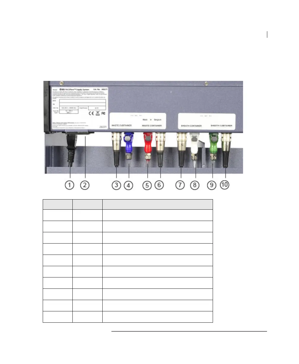
The following figure shows the connector positions on the
back of the BD FACSFlow supply system. The table shows
the functions of each sensor cable and tubing.
.
Location Color Function
1 black AC plug
2black1 A T fuse
3 silver Waste cubitainer sensor connector
4 blue Waste cubitainer tubing connector
5 red Waste container tubing connector
6 silver Waste container sensor connector
7 silver Sheath container sensor connector
8 white Sheath container tubing connector
9 green Sheath cubitainer tubing connector
10 silver Sheath cubitainer sensor connector