The MC50 function provides an interlock of Relay 1 and Relay
2 triggered by Inputs 1 and 2, with door position switch inputs
on Input 3 for Input 1 and Input 4 for Input 2. Only one relay
will be allowed to operate at a time thus making the two relays
interlocked or mutually exclusive. In order to activate a relay, its
corresponding position switch input must be closed. Adjustable
parameters include H1 for activation hold time of Relay 1 and H2
for activation hold time of Relay 2. A re-activation or maintaining
of an input while its respective relay is activated will restart the
hold timer and keep the relay active.
NOTE: The door position switch must have a closed
contact when the door is closed and an opened
contact when it is not.
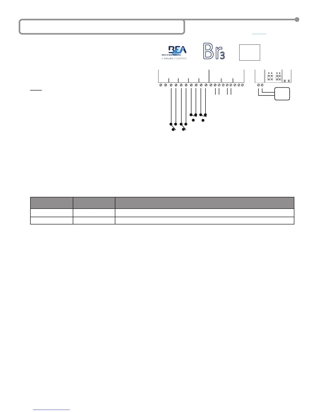
A typical application is to have a pair of doors on a clean room in
which only one door can be opened at a time. Each door would
have a push-plate and a door position switch. For this scenario
each door’s push-plate would be wired to Input 1 and Input
2, with the door position switches wired to Input 3 and Input 4
respectively, door controller 1 would be wired to Relay 1 and
door controller 2 would be wired to Relay 2. An example wiring
diagram for this scenario is shown.
MC50 SETUP
1. Wire the Br3 accordingly.
2. Select the MC50 as the function according to the steps outlined in Section 5 – Selecting the Function.
• Press and hold both push buttons (INCR & PARAM) for three (3) seconds to activate the display.
• Press the INCR button to toggle through each function and select 50.
3. Set the MC50 parameters according to the steps outlined in Section 5 – Selecting the Function.
• Press PARAM button to cycle through and set the parameters.
• Press the INCR button to increment the parameter’s value.
Parameters for the MC50 function are shown in the chart. Set the parameters as needed for the application, and wait for the display to
become inactive to save the conguration.
PARAMETER
(PARAM Button)
DESCRIPTION POSSIBLE VALUES
(INCR Button)
H1
Relay 1 hold time
‘00’ through ‘60’. Relay 1 hold time will not begin counting down until the release of Input 1.
H2
Relay 2 hold time
‘00’ through ‘60’. Relay 2 hold time will not begin counting down until the release of Input 2.
4. Once programming is complete, test the Br3. Wait until both doors are closed then trigger Relay 1 via Input 1. Ensure that Relay 1 changes
state and its hold time and is as programmed. The display will show
R1 when Relay 1 is energized. Test the interlock by attempting to trigger
Relay 2 via Input 2 while door 1 is still open. Relay 2 should NOT activate due to the rst position switch being opened. Let Relay 1 timeout
and the door to close. The display will show 50 when Relay 1 is de-energized. Once the rst position switch is closed trigger Relay 2 via
Input 2. Ensure that Relay 2 changes state and its hold time and is as programmed. The display will show R2 when Relay 2 is energized.
Test the interlock by attempting to trigger Relay 1 via Input 1 while door 2 is still open. Relay 1 should NOT activate due to the second
position switch being opened. The display will show 50 when Relay 2 is de-energized.
5. Upon completion of the above steps, walk test the door to ensure all functions, timers, sensors, etc. are working as intended, and that the
system is in compliance with all applicable standards (i.e. ANSI A156.10, A156.19).
6I Function 50 - Interlock Timer (MC50)
Page 11 of 15 75.5501.02 EN 20091102 (75.5500)
GND
IN-1
GND
IN-2
GND
IN-3
GND
IN-4
1 2 3 4
WET
WET
WET
NC
NO
COM
NC
NO
COM
12-24V
AC/DC
RELAYS
1 2
POWER
RELAY 1
INCR.
PARAM
SETUP
DC AC
DRY WET
INPUTS
5 0
NC
NO
COM
3
Br
3
CAUTION: RELAY 1 WET
OUTPUT OPTION
IS ACTIVE FOR
ALL FUNCTIONS.
12 to 24
VAC/VDC
+/- 10%
Directly to Activation Circuit of
Door Control #1 and Door Control
Activation Circuit of Door #2.
Inputs 1 & 2 are activation
inputs for Doors 1 & 2.
Inputs 3 & 4 are for the door position switch for inputs
1 & 2 respectively. Switch is closed when door is closed.