The LE21 function provides activation of Relay 1 with an inhibitor
of activation for Input 1 until Input 2, Input 3 or ‘WET’ Input is
triggered, which all activate Relay 1. Additionally Input 4 provides
a door position switch input for which closing it will re-inhibit Input 1.
Adjustable parameters include H1 for activation hold time of Relay 1.
NOTE: The door position switch must have a closed contact when
the door is closed and an opened contact when it is not.
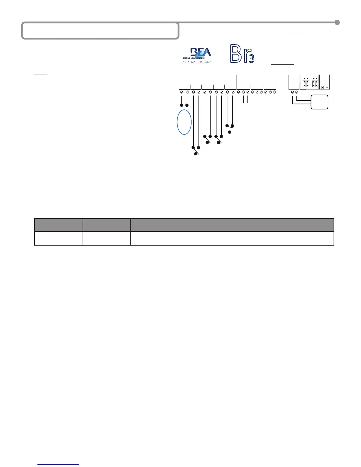
A typical application is a ‘Low-Energy’ situation in which you
have only ‘Knowing-Act’ activation devices such as push-plates,
a re-activation device, such as a SuperScan, on the door for safety
and a door position switch. For this scenario the push-plates
would be wired to Inputs 2 and/or 3, the SuperScan would be
wired to Input 1, a door position switch on Input 4 and the door
controller on Relay 1. When the door position switch on Input 4
is closed, the SuperScan Input is ignored (inhibited) and only
becomes a re-activation device (uninhibited) after an activation
on Input 2 or Input 3. The SuperScan on Input 1 will remain
uninhibited until the door is closed again, closing Input 4.
An example wiring diagram for this scenario is shown.
NOTE: While the ‘WET’ Input is not involved in our typical application,
it will still function as Input 2 and Input 3.
LE21 SETUP
1. Wire the Br3 accordingly.
2. Select the LE21 as the function according to the steps outlined in Section 5 – Selecting the Function.
• Press and hold both push buttons (INCR & PARAM) for three (3) seconds to activate the display.
• Press the INCR button to toggle through each function and select 2 1.
3. Set the lone LE21 parameter according to the steps outlined in Section 5 – Selecting the Function.
• Press PARAM button to cycle through and set the parameters.
• Press the INCR button to increment the parameter’s value.
The single parameter for the LE21 function is shown in the chart. Set it as needed for the application, and wait for the display to become
inactive to save the conguration
PARAMETER
(PARAM Button)
DESCRIPTION POSSIBLE VALUES
(INCR Button)
H1
Relay 1 hold time
‘00’ through ‘60’. Relay 1 hold time will not begin counting down until the release of an
activation input.
4. Once programming is complete, test the Br3. Attempt to trigger the timer via the re-activation device tied to Input 1. Ensure that Relay 1 does
NOT energize as it should be inhibited. The display should still show
21 since Relay 1 is de-energized. Now trigger the timer via Input 2, Input
3 or ‘WET’ Input. Ensure that Relay 1 activates and its hold time and is as programmed. The display will show R1 when Relay 1 is energized.
Before the door closes attempt to re-activate the timer via the device tied to Input 1. The door should re-open and the timer should restart. Once
again observe the relay hold time and ensure that it is as programmed. Let the door close to close Input 4 via the door position switch. Once
again attempt to trigger the timer via the re-activation device tied to Input 1. Ensure that Relay 1 does NOT energize as it should be re-inhibited.
5. Upon completion of the above steps, walk test the door to ensure all functions, timers, sensors, etc. are working as intended, and that the system
is in compliance with all applicable standards (i.e. ANSI A156.10, A156.19).).
6C Function 21 - Inhibitor (LE21)
GND
IN-1
GND
IN-2
GND
IN-3
GND
IN-4
1 2 3 4
WET
WET
WET
NC
NO
COM
NC
NO
COM
12-24V
AC/DC
RELAYS
1 2
POWER
RELAY 1
INCR.
PARAM
SETUP
DC AC
DRY WET
INPUTS
2 1
NC
NO
COM
3
Br
3
CAUTION: RELAY 1 WET
OUTPUT OPTION
IS ACTIVE FOR
ALL FUNCTIONS.
12 to 24
VAC/VDC
+/- 10%
Directly to Activation
Circuit of Door Control
or Other Device.
Inputs 2 & 3 can be used for Pushplate
input or other activation device.
Input 4 is for the door position switch.
Switch is closed when door is closed.
Input 1 for SuperScan
at approach side.
‘ WE T ’
12 to 24
VAC/VDC
+/- 10%
INPUT
+ -
Page 5 of 15 75.5501.02 EN 20091102 (75.5500)