The MC55 function provides an interlock ratchet of Relay 1 and
Relay 2 triggered by Inputs 1 and 2, with door position switch
inputs on Input 3 for Input 1 and Input 4 for Input 2. Only one
relay will be allowed to operate at a time thus making the two
relays interlocked or mutually exclusive. In order to activate a
relay, its corresponding position switch input must be closed.
Each trigger of an input will change the state of its respective
relay. MC55 has NO adjustable parameters. If the input is
maintained, its relay will only change state once. The input must
then be opened and re-closed for a change of state.
NOTE: The door position switch must have a closed
contact when the door is closed and an opened
contact when it is not.
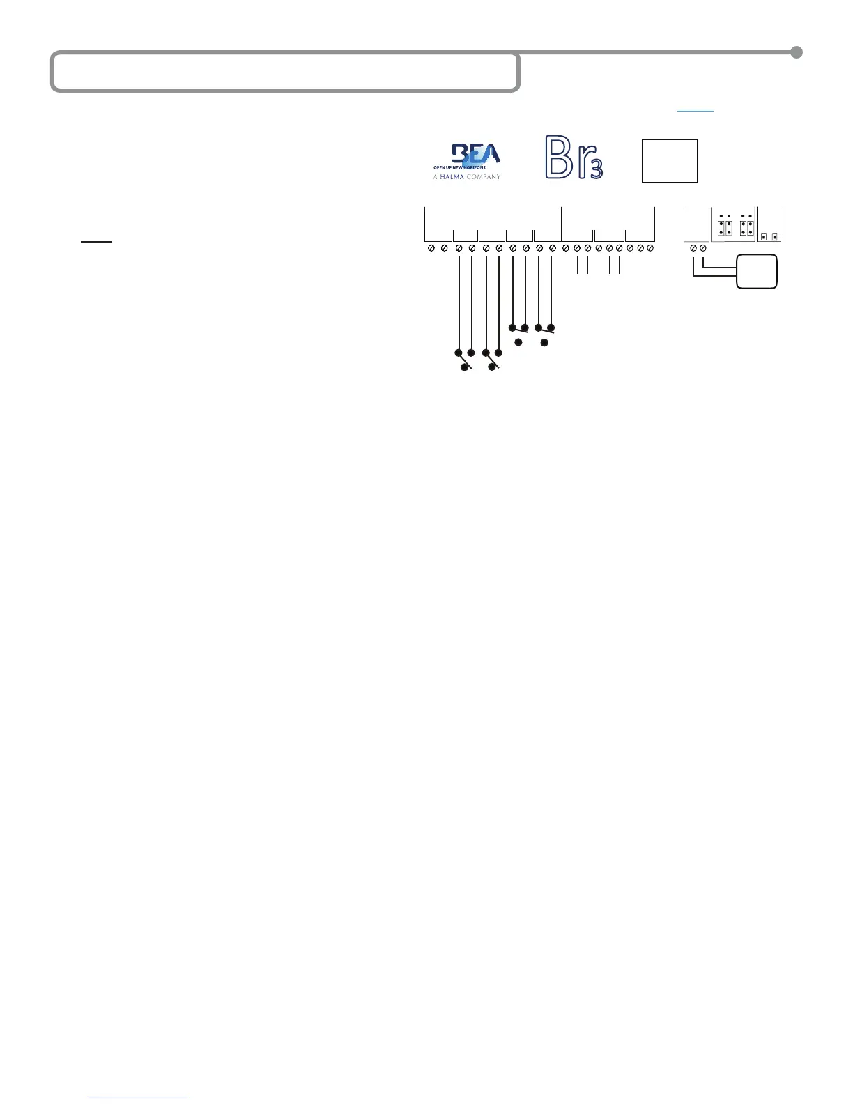
A typical application is to have a pair of doors on a clean room in
which only one door can be opened at a time. Each door would
have a set of push-plates connected to it in the instance that a
single hold time will not suit all users of the door. Each door would
also have a door position switch. For this scenario door number
1 and 2 push plates shall be wired in parallel to inputs 1 and 2
respectively, with the door position switches wired to Input 3 and
Input 4 respectively, door controller 1 would be wired to Relay
1 and door controller 2 would be wired to Relay 2. An example
wiring diagram for this scenario is shown below.
MC55 SETUP
1. Wire the Br3 accordingly.
2. Select the MC55 as the function according to the steps outlined in Section 5 – Selecting the Function.
• Press and hold both push buttons (INCR & PARAM) for three (3) seconds to activate the display.
• Press the INCR button to toggle through each function and select 55.
3. There are NO parameters to set for the MC55 as the state of Relay 1 and Relay 2 are not based on time, so just wait for the display to
become inactive to save the conguration.
4. Once programming is complete, test the Br3. Wait until both doors are closed then trigger Relay 1 via Input 1. Ensure that Relay 1 changes
state and that is maintained. The display will show R1 when Relay 1 is energized. Test the interlock by attempting to trigger Relay 2 via
Input 2. Relay 2 should NOT activate due to the rst position switch being opened. Now trigger Relay 1 again via Input 1 and ensure Relay
1 changes state again. The display will show 55 when Relay 1 is de-energized. Once the rst position switch is closed trigger Relay 2 via
Input 2. Ensure that Relay 2 changes state and that is maintained. The display will show R2 when Relay 2 is energized. Test the interlock
by attempting to trigger Relay 1 via Input 1. Relay 1 should NOT activate due to the second position switch being opened. Now trigger Relay
2 again via Input 2 and ensure Relay 2 changes state again. The display will show 55 when Relay 2 is de-energized.
5. Upon completion of the above steps, walk test the door to ensure all functions, timers, sensors, etc. are working as intended, and that the
system is in compliance with all applicable standards (i.e. ANSI A156.10, A156.19).
6J Function 55 - Interlock Ratchet (MC55)
75.5501.02 EN 20091102 (75.5500) Page 12 of 15
GND
IN-1
GND
IN-2
GND
IN-3
GND
IN-4
1 2 3 4
WET
WET
WET
NC
NO
COM
NC
NO
COM
12-24V
AC/DC
RELAYS
1 2
POWER
RELAY 1
INCR.
PARAM
SETUP
DC AC
DRY WET
INPUTS
5 5
NC
NO
COM
3
Br
3
CAUTION: RELAY 1 WET
OUTPUT OPTION
IS ACTIVE FOR
ALL FUNCTIONS.
12 to 24
VAC/VDC
+/- 10%
Directly to Activation Circuit of
Door Control #1 and Door Control
Activation Circuit of Door #2.
Inputs 1 & 2 are activation
inputs for Doors 1 & 2.
Inputs 3 & 4 are for the door position switch for inputs
1 & 2 respectively. Switch is closed when door is closed.