The MC75 function provides a sequence for Relay 1 and/
or Relay 2 triggered by Input 1 or ‘WET’ Input. Adjustable
parameters include H1 for activation hold time of Relay 1, H2
for activation hold time of Relay 2 and D1 for delay between
activation of Relay 1 to Relay 2. A re-activation of Input 1 or
‘WET’ Input before the sequence expires will re-start both
hold timers and keep the relays active. A maintained input will
freeze both hold timers, thus keeping their relays active until the
input is released, which will allow the hold timers to expire and
deactivate the relays normally.
NOTE: The delay timer will only re one time during initial
activation or maintained input.
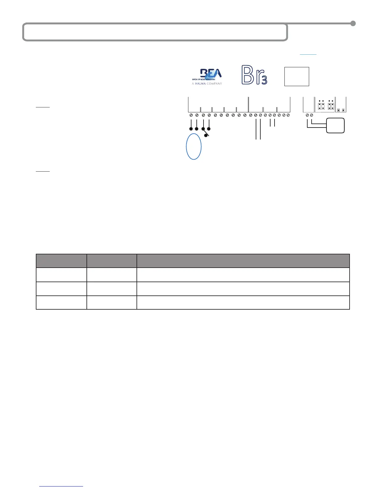
A typical application is a security door in which you have a card-
reader that supplies an output voltage to start the sequence to
unlock the security device, such as a Maglock or electric strike
and then activate the door controller. For this scenario the card-
reader would be wired to ‘WET’ Input, the security device would
be wired to Relay 1 and the door controller would be wired to
Relay 2. An example wiring diagram for this scenario is shown
below. An example wiring diagram for this scenario is shown
below.
NOTE: While the Input 1 is not involved in our typical
application, it will still function as ‘WET’ Input does if
used.
MC75 SETUP
1. Wire the Br3 accordingly.
2. Select the MC75 as the function according to the steps outlined in Section 5 – Selecting the Function.
• Press and hold both push buttons (INCR & PARAM) for three (3) seconds to activate the display.
• Press the INCR button to toggle through each function and select 75.
3. Set the MC75 parameters according to the steps outlined in Section 5 – Selecting the Function.
• Press PARAM button to cycle through and set the parameters.
• Press the INCR button to increment the parameter’s value.
Parameters for the MC75 function are shown in the chart. Set the parameters as needed for the application, and wait for the display to
become inactive to save the conguration.
PARAMETER
(PARAM Button)
DESCRIPTION POSSIBLE VALUES
(INCR Button)
H1
Relay 1 hold time
‘00’ through ‘60’ - Relay 1 hold time will not begin counting down until the release of Input 1 or
‘WET’ Input.
H2
Relay 2 hold time
‘00’ through ‘60’ - Relay 2 hold time will not begin counting down until the delay between
Relay 1 and Relay 2 expires.
D1
Delay between
Relay 1 and Relay 2
‘00’, ‘_1’ (1/4), ‘_2’ (1/2), ‘_3’ (3/4), ‘01’ through ‘60’ seconds. The delay time will begin
counting down with the activation of the sequence.
4. Once programming is complete, test the Br3. Trigger the sequence via Input 1 or ‘WET’ Input. Ensure that the sequence runs and the
relays activate and the timers are as programmed. The display will show
R1 when Relay 1 is energized, R2 when Relay 2 is energized and R=
when both Relay 1 and Relay 2 are energized at the same time.
5. Upon completion of the above steps, walk test the door to ensure all functions, timers, sensors, etc. are working as intended and that the
system is in compliance with all applicable standards (i.e. ANSI A156.10, A156.19).
6L Function 75 - 2 Relay Sequence (MC75)
75.5501.02 EN 20091102 (75.5500) Page 14 of 15
GND
IN-1
GND
IN-2
GND
IN-3
GND
IN-4
1 2 3 4
WET
WET
WET
NC
NO
COM
NC
NO
COM
12-24V
AC/DC
RELAYS
1 2
POWER
RELAY 1
INCR.
PARAM
SETUP
DC AC
DRY WET
INPUTS
7 5
NC
NO
COM
3
Br
3
CAUTION: RELAY 1 WET
OUTPUT OPTION
IS ACTIVE FOR
ALL FUNCTIONS.
12 to 24
VAC/VDC
+/- 10%
To Activation Circuit
of Door Control.
Input 1 is for an
additional ‘Dry’
Input Device.
‘ WE T ’
12 to 24
VAC/VDC
+/- 10%
INPUT
+ -
Typically Connected to
Lock Device. When DC ‘WET’
Output is Selected for Relay 1,
COM Terminal is Positive (+).