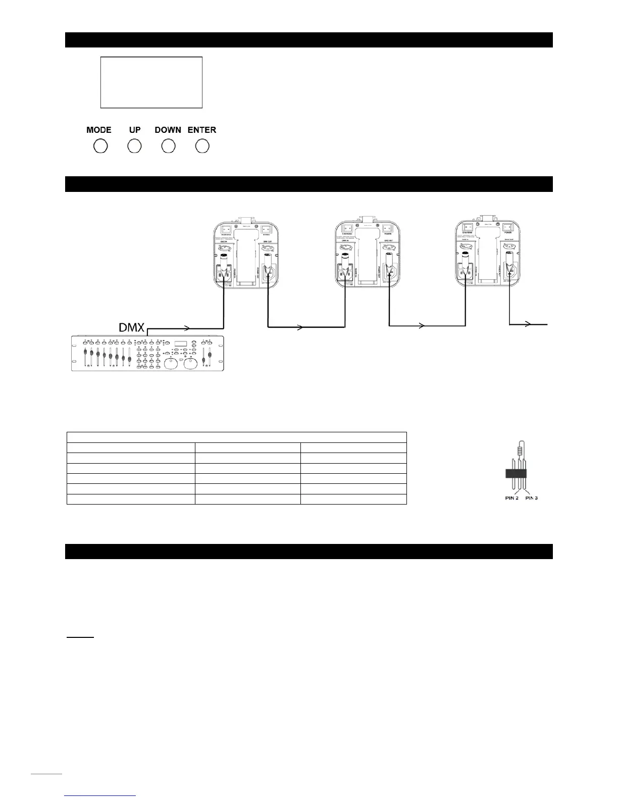
DISPLAY
The control board offer several features: you can simple set the starting address,
run the pre-programmed program or make a reset. The main menu is accessed
by pressing the Mode-button, browse through the submenu by pressing Up or
Down.
Press the Enter-button in order to select the desired menu.
You can change the selection by pressing Up or Down. Confirm every selection
by pressing the Enter-button.
You can leave every mode by pressing the Mode-button. The functions provided
are described later in this manual.
DMX-512 CONNECTION
If you are using a standard DMX controller, you can connect the DMX output of the controller directly to the DMX input of the
first unit in a DMX chain. Always connect the output of one unit with the input of the next unit until all units are connected.
5-pin XLR DMX Connectors.
Some manufactures use 5-pin DMX-512 data cables for DATA transmission in place of 3-pin. 5-pin DMX fixtures may be
implemented in a 3-pin DMX line. When inserting standard 5-pin data cables in to a 3-pin line a cable adaptor must be used.
The chart below details a proper cable conversion.
At the last fixture, the DMX cable has to be terminated. Solder a 120 Ohm resistor between signal (-) and signal (+) into a 3-pin
XLR connector and plug this into the DMX output of the last fixture in the chain.
MASTER/SLAVE OPERATION
The master/slave operation enables that several same units can be controlled by one “master” unit.
Connect the first unit “DMX OUT” socket with the second unit “DMX IN”, using a 3pin DMX Cable. Repeat this process with the
third, fourth etc. or see a above section “DMX-512 connection”. Choose the unit that will control all other and set this in master-
mode via display. The other units that must react on the master, you must set in slave-mode. The “Slave” will synchronously
follow the “Master” .
Noted: Any unit can be the “Master” or “Slave”.