AR6201 - RT6201 - RCU6201 - AR6203
Page 2-8 DV 14307.03 Issue 1 09/2013
2.4 Electrical Interface
2.4.1 Connectors and Pin Assignment for AR6201, AR6203 and RT6201
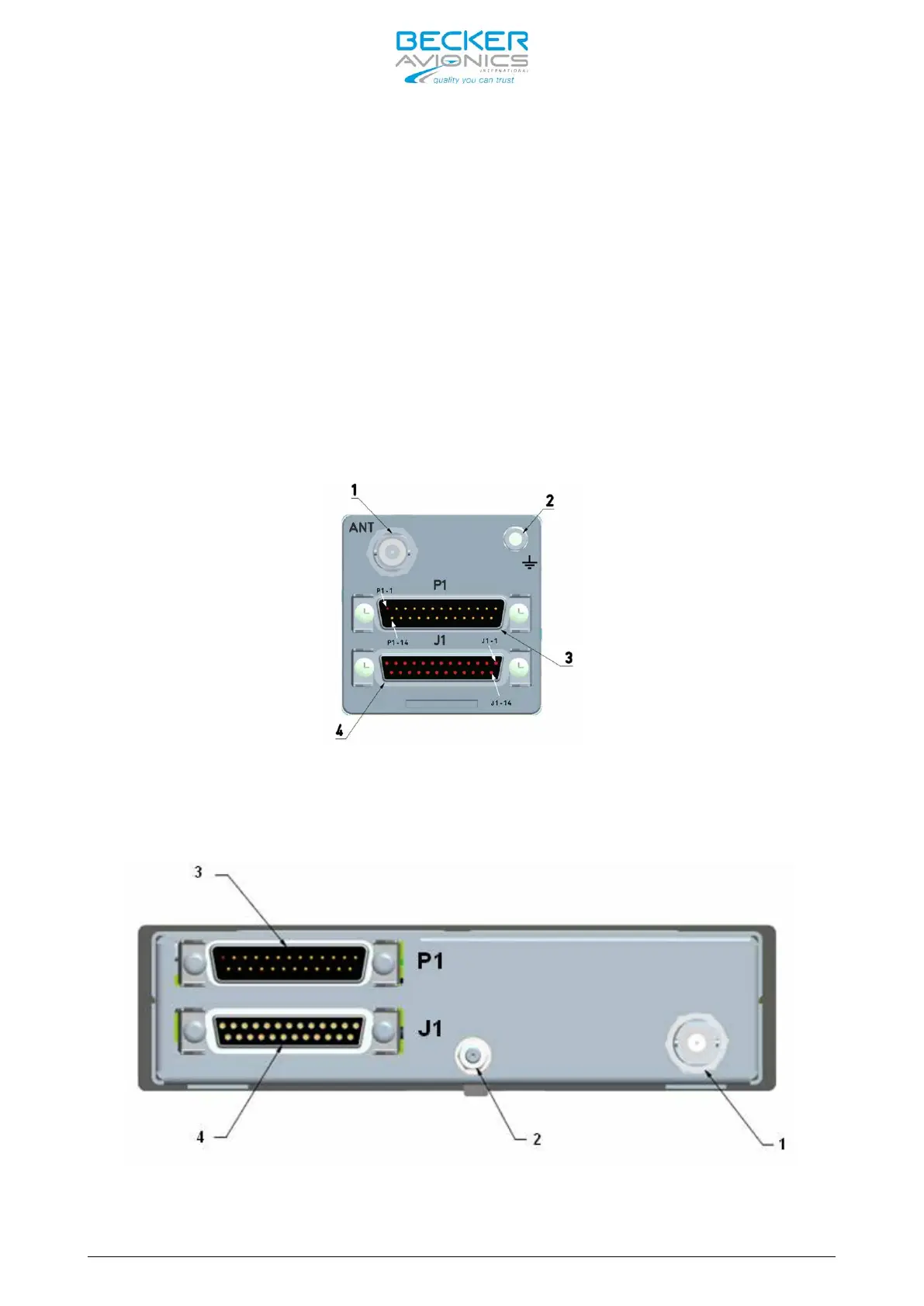
Antenna Connector (Position 1)
The antenna connector (Figure 2-14, position 1) is a BNC type. The antenna
port is designed for operating with a nominal impedance of 50 Ohm.
Grounding Bolt (Position 2)
The transceiver has a M4 threaded grounding bolt (Figure 2-14,position 2)
allowing a low impedance grounding of the unit, which is essential to avoid
damage or malfunction in the case of indirect lightning, EMI and HIRF
conditions.
Figure 2-14: Male P1 and female J1 connectors
on back plate AR6201 and RT6201
Figure 2-15: Male P1 and female J1 connectors on back plate AR6203

 Loading...