12
Assembly and Operating Instructions
Becker tubular drives with electronic limit switching can be parallel connected. The maximum switching contact loading of the
control device (timer, relay control, switch, etc.) must be observed.
Use external conductor L1 to control the up and down direction. Other devices or consumption units (lamps, relays, etc.) must
not be directly connected to the drive connection cables. For this purpose, the drives and additional units must be decoupled
by relay controls.
When installing the drive, an all-pole separation capability from the mains with at least 3mm contact opening width per pole
must be provided (EN 60335).
Attention: Only use mechanically or electrically locked switching elements with a marked zero position! This also applies when
drives with electronic and mechanical limit switching are used in the same system.
The changeover time for changing the running direction must be at least0,5 s. Switch and control must not execute simultane-
ous UP and DOWN commands.
To operate drives with electronic limit switching, only use control elements (time controls) which do not draw N potential via
the drive. The outputs of the control element must be potential-free in the neutral position.
Protect the electrical connections from damp.
Note
Becker tubular drives bear the CE mark. These drives comply with the valid EU guidelines and meet EMC
regulations.
If the drive is to be operated with units which contain sources of interference, the electrician must ensure
suitable interference suppression for the relevant devices.
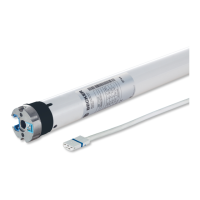
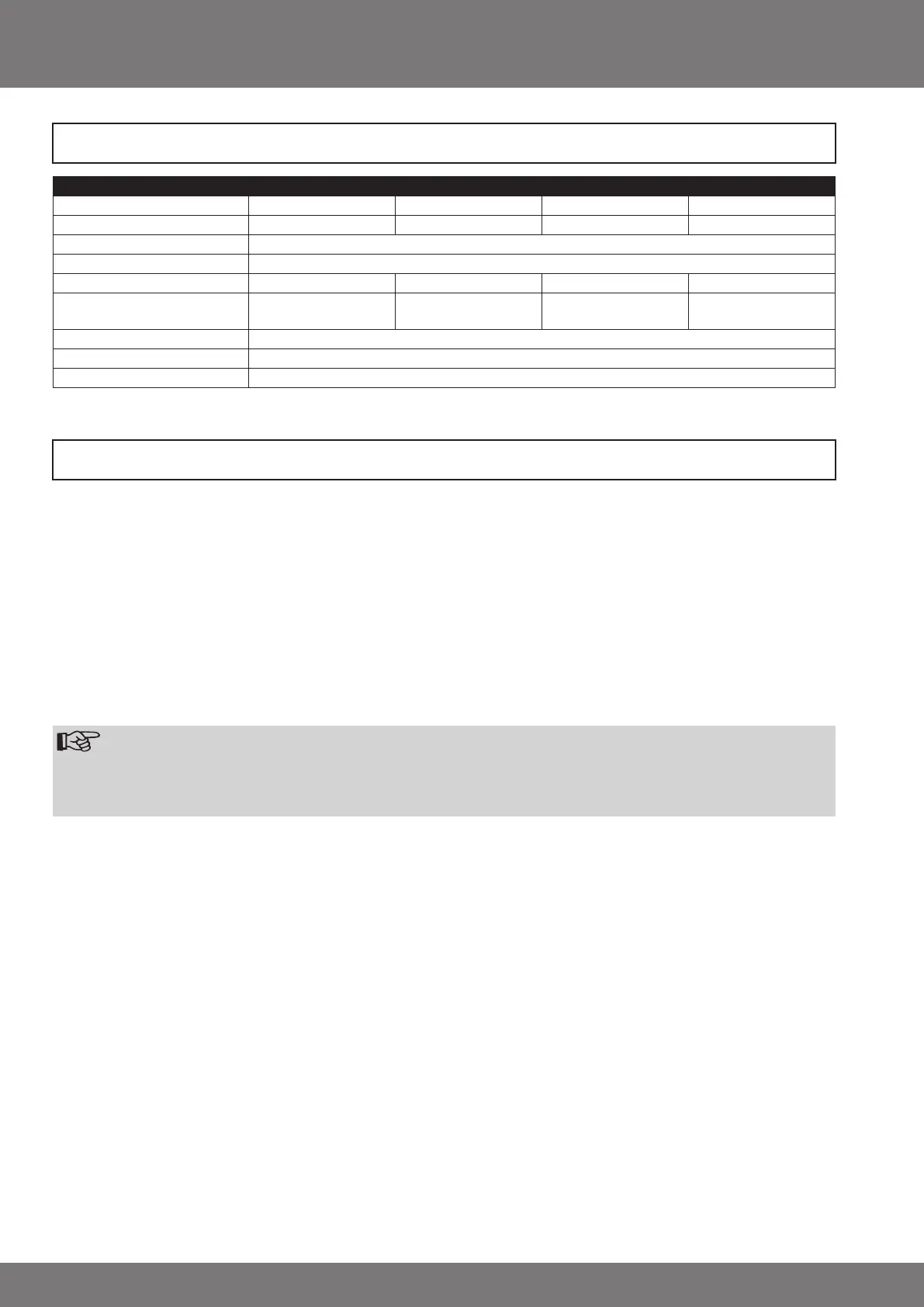
Technical Data
Information for the Electrician
Type P3/30PS P5/20PS P5/30PS P9/16PS
Nominal torque (Nm) 3 5 5 9
Output speed (min
-1
) 30 20 30 16
Limit switch range 64 revolutions
Mains voltage 230V/50Hz
Power consumption (W) 85 115 115 110
Nominal current consumption
(A)
0,36 0,47 0,47 0,47
Operating mode S2 4 min.
Protection class IP 44
Min. tube diameter (mm) 37