EasyManua.ls Logo

Becker R30-17 User Manual

Becker R30-17
28 pages
To Next Page IconTo Next Page
Page #1 background imageLoading...
Page #1 background image
R8-17...R30-17
Model: E22
en
Assembly and Operating Instructions
Tubular drives for roller shutters
Important information for:
• Fitters / • Electricians / • Users
Please forward accordingly!
These instructions must be kept safe for future reference.
Becker-Antriebe GmbH
Friedrich-Ebert-Straße 2-4
35764 Sinn/Germany
www.becker-antriebe.com
2010 301 266 0c03/05/2023
Question and Answer IconNeed help?

Do you have a question about the Becker R30-17 and is the answer not in the manual?

Becker R30-17 Specifications

General IconGeneral
BrandBecker
ModelR30-17
CategoryDC Drives
LanguageEnglish

Summary

General Information and Warranty

Explanation of Pictograms

Explains the meaning of warning and information icons used throughout the manual.

Warranty Terms

Details the warranty terms and conditions for the tubular drives.

Safety Instructions

User Safety Guidelines

Provides essential safety guidelines for users operating the tubular drives.

Installation and Commissioning Safety

Outlines safety procedures for installing and commissioning the drives.

Critical Injury Prevention Warnings

Highlights critical safety warnings to prevent serious injuries.

Property Damage Prevention

Provides important notices to prevent property damage.

Intended Use and Cable Assembly

Plug-in Connecting Cable Assembly

Step-by-step guide for connecting and disconnecting the drive's power cable.

Assembly for Second Escape Route Applications

Drive Assembly

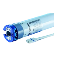
Instructions on how to assemble the tubular drive unit.

Drive Adapter Assembly

Guidance on attaching the drive adapter to the motor shaft.

Drive Adapter Disassembly

Steps for safely removing the drive adapter.

Mounting Drive in Tube

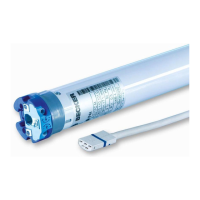
Procedure for installing the drive into the roller shutter tube.

Setting & Deleting Limit Positions for Second Escape Route

Setting Limit Positions via Programming Unit

How to set upper and lower limits using the electronic programming unit.

Deleting Limit Positions via Programming Unit

Procedure to erase set limit positions with the programming unit.

Adjusting Limit Positions with Rotary Switch or Locking Button

Deleting Limit Positions with Rotary Switch

Steps to delete limit positions using a mechanical rotary switch or button.

Assembly for Standard Roller Shutter Applications

Standard Drive Assembly

Guidance for assembling the drive for standard roller shutter systems.

Mounting Pin Assembly and Disassembly

Instructions for fitting and removing the mounting pin.

Standard Drive Adapter Assembly

Steps to assemble and disassemble the drive adapter.

Drive Adapter Assembly with Safety Catch

Attaching the drive adapter with a safety catch to the drive shaft.

Drive Adapter Disassembly with Safety Catch

Removing the drive adapter with a safety catch.

Mounting Drive in Tube (Standard)

Installing the drive into the roller shutter tube for standard applications.

Connecting Cable Routing

Routing and securing the electrical connecting cable.

Setting Limit Positions with Programming Unit (Standard)

Upper Stop to Lower Stop Setting

Setting limit positions from the top stop to the bottom stop.

Upper Point to Lower Point Setting

Setting limit positions from the upper point to the lower point.

Upper Stop to Lower Point Setting

Setting limit positions from the upper stop to the lower point.

Upper Point to Lower Stop Setting

Setting limit positions from the upper point to the lower stop.

Setting Limit Positions with Rotary Switch (Standard)

Upper Stop to Lower Stop Setting (Rotary)

Setting limit positions using a rotary switch from upper to lower stop.

Upper Point to Lower Point Setting (Rotary)

Setting limits with rotary switch from upper point to lower point.

Upper Stop to Lower Point Setting (Rotary)

Setting limits with rotary switch from upper stop to lower point.

Upper Point to Lower Stop Setting (Rotary)

Setting limits with rotary switch from upper point to lower stop.

Deleting Limit Positions with Rotary Switch

Obstruction and Blockage Detection

Details on how the drive detects obstructions and blockages.

Additional Upper Anti-Freeze Mechanism

Information on the anti-freeze feature and its activation.

Information for Electricians

Product Disposal Instructions

Instructions for environmentally sound disposal of the product.

Maintenance Recommendations

Information regarding the maintenance requirements of the drives.

Technical Data (Dia. 45)

Specifications and technical data for drives with 45mm diameter.

Troubleshooting Guide

Wiring Diagrams

Single Switch/Button Control Wiring

Wiring diagrams for controlling drives with a single switch or button.

Advanced Control System Wiring

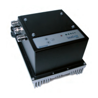
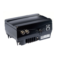
Wiring for advanced control systems using Centronic UnitControl UC42.

Declaration of Conformity

Related product manuals