Intended use
The type of tubular drive described in these instructions is intended solely for the operation of roller shutters.
Using both roller shutter escape sets (roller shutter escape crank sets for the second escape route and S60 roller shutter es-
cape drive adapter sets for the second escape route) and their correct assembly, the drives up to 20Nm are suitable for ap-
plications that represent a second escape route.
Due to patent agreements, delivery of drive type E22 is not permitted for roller shutter applications associated with es-
cape door solutions for homes, modular structures or commercial properties featuring a solid-wood and/or timber
frame design.
This type of tubular drive supports not only curtain attachment by means of springs but also mechanical anti-lifting devices (e.g.,
Zurfluh-Feller, Simu, GAH Alberts and Deprat). These are detected automatically.
For sun protection applications, please use only the types of tubular drive designed for this purpose.
This type of tubular drive is designed for use in single systems (one drive per barrel).
The tubular drive must not be used in potentially explosive areas.
The connecting cable is not suitable for transporting the drive. Always carry the drive by the housing tube.
Other applications, uses and modifications are not permitted in order to protect the safety of the users and others, since these ac-
tions can impair the system’s safety and carry the risk of personal injury and property damage. The drive manufacturer does not
accept liability for damages or injury arising from such actions.
Always observe the information in these instructions when operating or repairing the system. The drive manufacturer does not ac-
cept liability for damage or injury resulting from improper usage.
Attention
Only use anti-lifting devices if the roller shutter laths are sufficiently strong. The closed
curtain must not project beyond the guide tracks or else there is a risk of the joint between
the top two laths being subjected to excessive strain and getting damaged.
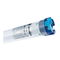
Assembling and disassembling the plug-in connecting cable
Caution
The power supply to the connecting cable must be disconnected prior to assembly/disas-
sembly.
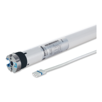
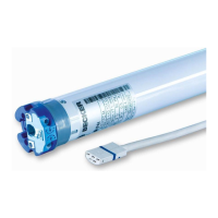
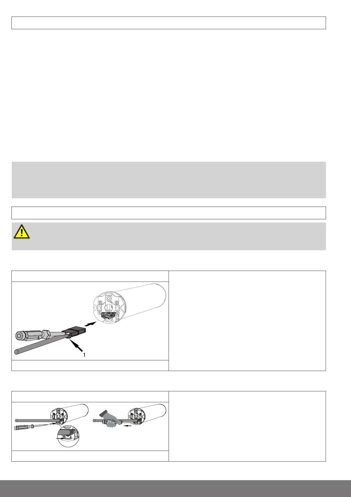
Assembling the plug-in connecting cable
Ø35/Ø45/Ø58 Insert the dead connecting cable into the drive head until the
locating lug clicks into place in the drive. If necessary, use a
suitable flathead screwdriver to assist with insertion. Set the
screwdriver into one of the two plug grooves provided for this
purpose.
Check that the cable is properly engaged.
1 = locating lug
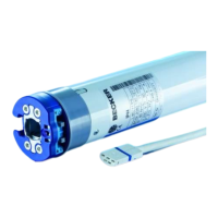
Disassembling the plug-in connecting cable for tubular drives
Ø45/Ø58
Insert a suitable flathead screwdriver right into the recess of the
locating latch, so that the latch releases the locating lug from
the plug.
Now you can pull out the connecting cable along with the flat-
head screwdriver.
A = locating latch
6-en