Assembly for applications that represent a second escape route
Attention
The roller shutter escape crank set and S60 roller shutter escape drive adapter set must
only be used with tubular drives up to 20Nm.
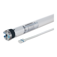
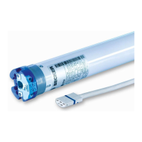
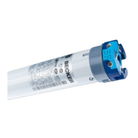
Assembling the drive
Attention
To connect the drive to the driven part, solely mechanical accessory components made by
the drive manufacturer from the current product catalogue may be used.
Prior to mounting, the fitter must ensure that the masonry and the system being motorised are sufficiently robust (drive torque plus
weight of the shading solution).
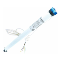
Caution
Electrical connections may only be carried out by a qualified electrician. Prior to assembly,
the power supply must be disconnected and secured. Please give the enclosed connection
information to the responsible electrical contractor.
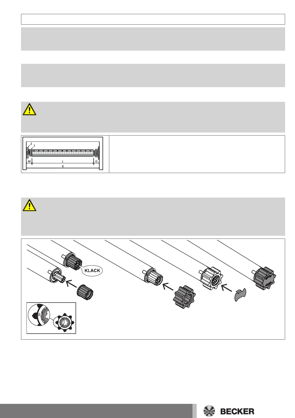
Calculate the space required at the side (M) by measuring the drive head (1) and wall
bracket (2). The clear dimension of the box (X) minus the space required at the side
(M) and idler (G) gives the length (L) of the barrel: L=X-M-G.
The space required at the side (M) varies depending on the combination of drive and
wall bracket.
Then mount the wall bracket and idler. Ensure that the barrel is aligned at right angles to the wall and that sufficient axial play is al-
lowed for the mounted system.
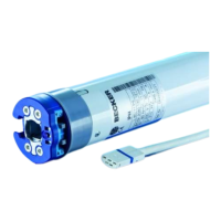
Assembling the drive adapter
Caution
Never screw the drive adapter to the shaft. Make absolutely sure that the installation dir-
ection of the drive adapter is correct! The arrows on the white ring of the drive adapter
must be pointing in the wind-up direction.
Please ensure that the emergency crank handle is unhooked before motorised operation.
7-en