Operating Instructions
14
Information for the Electrician
Becker tubular drives with mechanical limit switching must not be connected in parallel. For simultaneous control of several
drives use appropriate Becker controls.
To control the up and down direction, use external conductor L1.
Other devices or consumption units (lamps, relays, etc.) must not be connected directly to the drive connection cables. For
this purpose, the drives and additional units must be decoupled by relay controls. When installing the drive, an all-pole sepa-
ration capability from the mains with at least 3mm contact opening width per pole must be provided (VDE 0700).
Attention
Only use mechanically or electrically locked switching elements with a marked zero position! Protect the
electrical connections against dampness.
Becker tubular drives bear the CE mark. These drives comply with the valid EU guidelines and meet EMC regulations.
If the drive is operated with units containing sources of interference, the electrician must ensure suitable interference sup-
pression for the relevant devices.
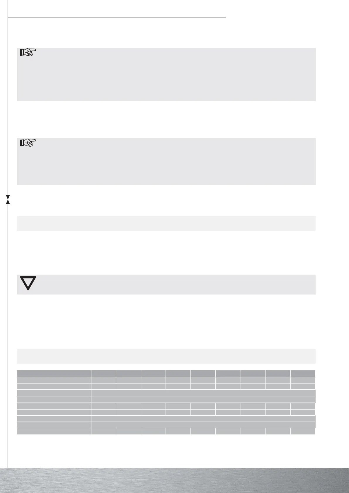
Technical data
Setting the top end position
Press the UP switch. The drive runs upwards and rolls the roller shutter or blind up. Extend or reduce the switch-off point by
turning the corresponding setting screw.
Note
The length of the roller shutter must not exceed the window height plus the clear height of the roller
shutter box. If locking straps are used, the shutter must not protrude over the guide rails in the closed
position, as otherwise there is the risk that the link between the two top laths will be too heavily loaded.
In order to take account of any changes in length of the roller shutter, remove the stop angle or stopper
on the end strip. Protect the individual laths against lateral movement.
During commissioning and later use, ensure that the roller shutter runs UP and DOWN smoothly and
trouble-free.
Functional check
As a final control, allow the roller shutter to run in both directions as far as the end position. If locking straps are fitted, check
that they function perfectly, in accordance with the manufacturer’s instructions. They must be securely engaged and press
the shutter onto the window sill. The locking straps must press the top plate in an upright position against the roller shutter
box.
Note
Becker tubular drives are designed for short-time operation (S2/KB 4 min). A fitted thermo protection
switch prevents overheating of the tubular drive. During commissioning (long roller shutter, or long run-
ning time), triggering of the thermoswitch may occur. The drive is then switched off. After a short cool-
ing-down period, the system is ready for operation again.
The drive will only reach the full duty cycle when it has cooled down to ambient temperature. Avoid re-
peated actuation of the thermo protection switch.
epyT M02/5P M03/5P M61/9P M9/31P M71/8R M71/21R M71/51R M71/02R M71/52R
)mN(euqrotlanimoN 5 5 9 31 8 21 51 02 52
(deepstuptuOMpU
1-
) 02 03 61 9 71 71 71 71 71
egnarnoitisoptimillaniF 83
egatlovsniaM zH05/CAV032
)W(noitpmusnocrewoP 511 511 011 511 511 521 551 571 591
)A(noitpmusnoctnerruclanimoN 74,0 74,0 74,0 74,0 5,0 35,0 76,0 77,0 48,0
edomgnitarepO .niM42S
ssalcnoitcetorP 44PI
)mm(retemaidlerrabmuminiM 73 73 73 73 74 74 74 74 74