List of figures
EL2911 and EL2911-220060 Version: 2.0.0
List of figures
Fig. 1 Slot and key system and screwless (spring-loaded) connection system ..................................... 14
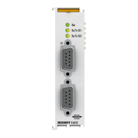
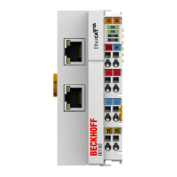
Fig. 2 Bus Coupler (EtherCAT) .............................................................................................................. 15
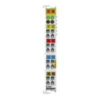
Fig. 3 Overview of EtherCAT Terminals................................................................................................. 16
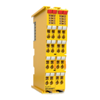
Fig. 4 EL2911 - TwinSAFE potential feed terminal with 4 fail-safe inputs.............................................. 19
Fig. 5 External load ................................................................................................................................ 22
Fig. 6 protected wiring............................................................................................................................ 23
Fig. 7 Characteristic curve of the inputs................................................................................................. 26
Fig. 8 EL2911 dimensions...................................................................................................................... 26
Fig. 9 Spring contacts of Beckhoff I/O components............................................................................... 28
Fig. 10 Installation position and minimum distances................................................................................ 29
Fig. 11 Thermally unfavorable arrangement of the TwinSAFE terminals................................................. 31
Fig. 12 Thermally favorable arrangement of the TwinSAFE terminals..................................................... 31
Fig. 13 Installation on the mounting rail ................................................................................................... 32
Fig. 14 Removal of mounting rails............................................................................................................ 33
Fig. 15 PE power contact ......................................................................................................................... 34
Fig. 16 Connection of a cable to a terminal point..................................................................................... 35
Fig. 17 EL2911 - pin assignment ............................................................................................................. 36
Fig. 18 Cable routing................................................................................................................................ 37
Fig. 19 Adding an EL2911........................................................................................................................ 38
Fig. 20 Delete project data ....................................................................................................................... 39
Fig. 21 Address settings on TwinSAFE terminals with 1023 possible addresses.................................... 41
Fig. 22 Starting the automatic import from the I/O configuration.............................................................. 42
Fig. 23 Selection from the I/O tree ........................................................................................................... 42
Fig. 24 Creating alias devices by the user ............................................................................................... 43
Fig. 25 Linking tab of the alias device...................................................................................................... 43
Fig. 26 Connection tab of the alias device ............................................................................................... 44
Fig. 27 EL2911 parameters...................................................................................................................... 44
Fig. 28 EL2911 process image ................................................................................................................ 46
Fig. 29 Typical reaction time .................................................................................................................... 47
Fig. 30 Worst-case reaction time ............................................................................................................. 48
Fig. 31 EL2911 status and diagnostics LEDs .......................................................................................... 49
Fig. 32 ESI/XML message text................................................................................................................. 52
Fig. 33 Startup list .................................................................................................................................... 52
Fig. 34 Diag history .................................................................................................................................. 53
Fig. 35 Diag history – advanced settings ................................................................................................. 53
Fig. 36 Unique serial number of a TwinSAFE terminal ............................................................................ 54
Fig. 37 EL2911 EC Declaration of Conformity ......................................................................................... 59