Installation
1c.
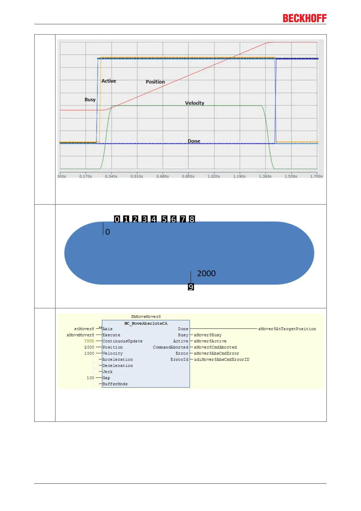
The diagram now indicates that the mover is active and has assumed the specified velocity over the
travel path. At target position (2000) the velocity has reduced, and the activity of the mover has
ceased.
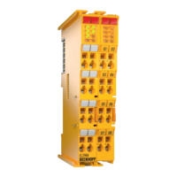
1d.
The mover no. 9 has now arrived at the previously set position.
2a.
A further mover is now parameterized. Mover 8 is also instructed to move to position 2000, with a
velocity of 1000. The distance of 100 remains the same. Since mover 9 is already at this position, a
typical collision scenario would arise. However, both movers are declared with a gap of 100. This
means that mover 8 moves to position 1800 and keeps a distance of 100 to mover 9.
eXtended Transport System Start-Up42
Version: 1.2