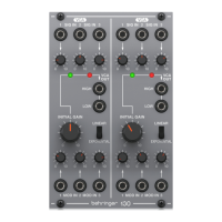
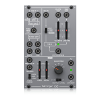
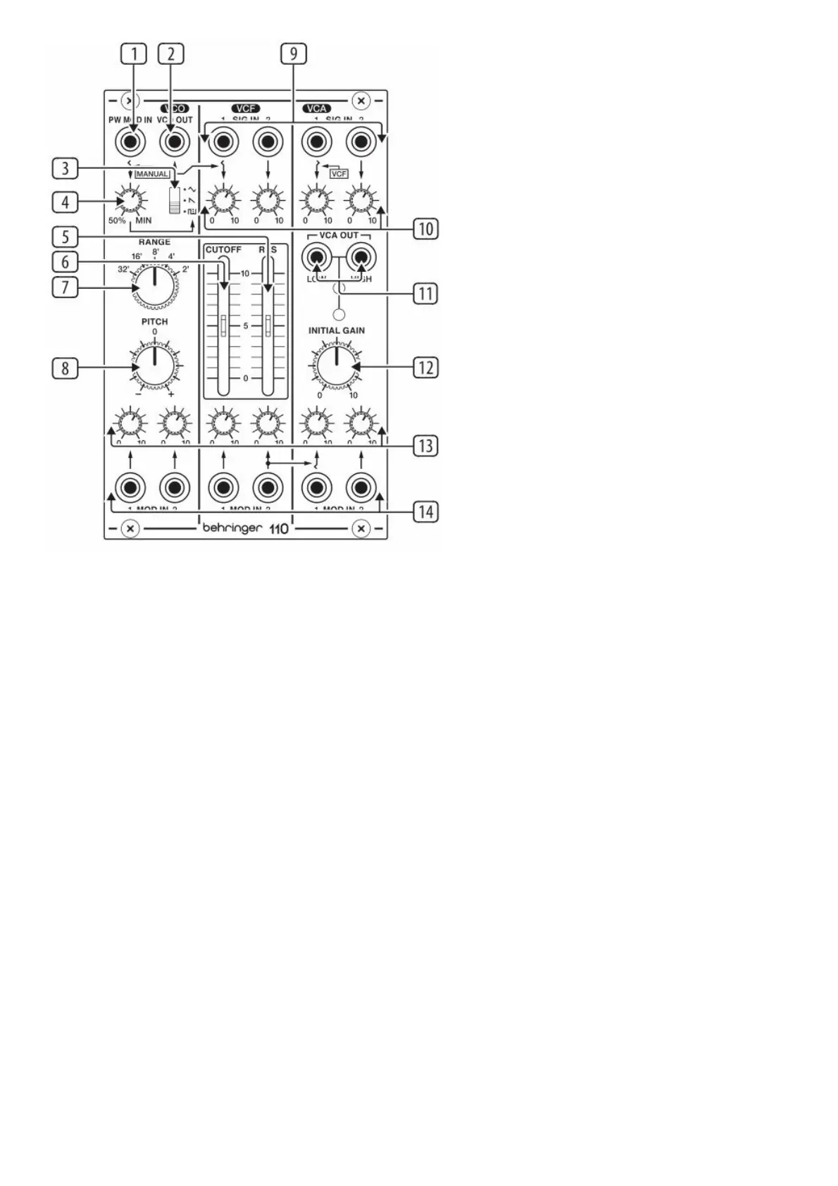
(1) PW MOD – Accepts a voltage from another module to control the pulse width. When a jack is inserted the MOD
MANUAL control acts as a MOD input level control.
(2) VCO OUT – Send the VCO signal to another source via 3.5 mm TS cable.
(3) WAVEFORM – Select triangle, sawtooth or pulse waveforms for the VCO.
(4) MOD MANUAL – Sets the ratio between the upper and lower portions of the pulse wave.
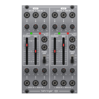
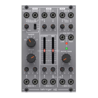
(5) RES – Boosts the resonance frequencies selected with the CUTOFF FREQ slider, potentially causing VCF
oscillation.
(6) CUTOFF FREQ – Adjusts the cutoff frequency of the low-pass filter.
(7) RANGE – Sets the pitch range of the VCO in octave steps.
(8) PITCH – Fine tunes the pitch.
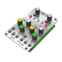
(9) VCF/VCA SIG IN – Connect incoming signals via 3.5 mm TS cables.
(10) SIG LEVEL – Adjust the level of the signals connected to the inputs.
(11) VCA OUT – Sends the VCA signal via 3.5 mm TS cable with either high or low signal levels.
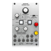
(12) INITIAL GAIN – Adjusts the initial gain level when there is no control voltage present. The adjacent LEDs will
light to indicate signal (green) and overload (red).
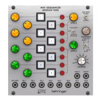
(13) MOD LEVEL – Adjusts the level of the signal connected to the associated MOD IN jack.
(14) MOD IN – Accepts voltages that control or modulate the VCO, VCF or VCA.
Power Connection